A method and system for locating base station interference

A technology for locating base stations and base stations, which is applied in the field of communication, and can solve problems such as failure to work normally, interference on the live network, and inability to determine the type of interference

Active Publication Date: 2020-03-31
ZTE CORP
View PDF7 Cites 0 Cited by
  • Summary
  • Abstract
  • Description
  • Claims
  • Application Information

AI Technical Summary

Problems solved by technology

[0004] With the vigorous development of mobile communication, there are tens of millions of 2G, 3G and 4G base stations in the current network, and the electromagnetic environment is complex.
Due to various reasons, the current base station is often affected by external interference and cannot work normally
At present, due to network planning and other reasons in China, the signal coverage in some areas is not good. Privately erected micro-signal boosters, such as "mobile phone companion", to enhance coverage, but such equipment has not been approved by the telecommunications department, causing serious damage to existing network base stations. Interference causes the base station to collapse; 2G, 3G and 4G co-site, due to the small protection interval, leads to adjacent frequency interference; with the wind and rain, the connection of the antenna feeder system becomes worse, and it will also cause serious damage to itself. Interference: With the development of information security, a large number of pseudo base stations also appear. The pseudo base stations not only eavesdrop on people's information, but also cause great interference to the existing network, resulting in a severe decline in the performance of the existing network.
Due to the inability to determine the type of interference and the cause of the interference source, the interfered base station cannot remove or reduce the interference, resulting in failure to work normally

Method used


Image

  • A method and system for locating base station interference
  • A method and system for locating base station interference
  • A method and system for locating base station interference

Examples


Embodiment

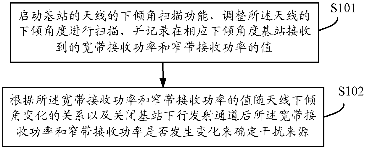
[0071] Such as figure 2 As shown, this embodiment provides a method for locating base station interference, including:

[0072] S101: Start the downtilt angle scanning function of the antenna of the base station, adjust the downtilt angle of the antenna to scan, and record the values ​​of the wideband received power and the narrowband received power received by the base station at the corresponding downtilt angle;

[0073] Adjust the downtilt angle of the antenna to scan, such as scanning from 0 degrees to X degrees, where X degrees is the maximum adjustment angle of the antenna. In this embodiment, the broadband received power refers to the entire intermediate frequency band (filter intermediate frequency band) The receiving power within the narrowband receiving power refers to the receiving power within the bandwidth configured by the network management background.

[0074] In step S101, before starting the downtilt scanning function of the antenna of the base station, it ...


PUM


Abstract

Provided are a method and a system for locating interference to a base station. The method includes: enabling a downtilt angle scanning function of an antenna of a base station, adjusting a downtilt angle of the antenna, performing scanning and recording values of broadband receiving power and narrowband receiving power received by the base station at corresponding downtilt angles; and determining a source of interference according to a relationship of changes of the values of the broadband receiving power and the narrowband receiving power with the downtilt angle of the antenna and whether the values of the broadband receiving power and the narrowband receiving power change after a downlink transmission channel of the base station is turned off.

Description

technical field [0001] The present invention relates to the communication field, in particular to a method and system for locating base station interference. Background technique [0002] Currently mainstream 2G (Second Generation, second generation), 3G (3rd-Generation, third generation) and 4G (4th-Generation, fourth generation) base stations all use BBU (Base band Unit, baseband processing unit) + RRU (RadioRemote Unit, radio remote unit) + electric adjustable antenna architecture, by adjusting the downtilt angle of the electric adjustable antenna to achieve the adjustment of the cell coverage radius. The active antenna is a new framework in the form of the next-generation base station. The 3GPP (3rd Generation Partnership Project) organization has conducted in-depth research in LTE (Long Term Evolution, long-term evolution) Release12, and the R12 version will be released soon. The AAS (Adaptive Antenna System, Adaptive Antenna System) antenna can change the antenna incl...

Claims


Application Information

Patent Timeline
Patent Type & Authority Patents(China)
IPC IPC(8): H04W24/04H04W64/00
CPCH04B17/17H04B17/318H04B17/345H04W24/04H04W52/243
Inventor 成军平
Owner ZTE CORP
Why Eureka
Try Eureka