
Method, system and engraving machine for restoration and display of tool path trajectory

A display method and tool path technology, which is applied in the field of engraving machines, can solve problems such as difficult to ensure real-time drawing of tool paths, difficult implementation of tool path drawing functions, and increased computing burden on the processor, so as to achieve fast processing and good display effects , the effect of reducing performance requirements

Active Publication Date: 2018-09-18
刘云涛
View PDF3 Cites 0 Cited by
  • Summary
  • Abstract
  • Description
  • Claims
  • Application Information

AI Technical Summary

Problems solved by technology

In addition, if only the simple three-dimensional line drawing method is used without measures such as relief plane reconstruction and rendering, the effect of tool path drawing is not ideal. However, if the above measures are adopted, the processor will increase the computational burden, which is very difficult. Difficult to guarantee the real-time performance of toolpath drawing during machining
Based on the above reasons, in the low-end engraving and milling control system, due to the limitation of the processor, the above toolpath drawing function is difficult to implement or cannot achieve the expected effect

Method used


Image

  • Method, system and engraving machine for restoration and display of tool path trajectory
  • Method, system and engraving machine for restoration and display of tool path trajectory
  • Method, system and engraving machine for restoration and display of tool path trajectory

Examples


Embodiment Construction

[0045] The technical solutions of the present invention will be clearly and completely described below in conjunction with the accompanying drawings. Apparently, the described embodiments are part of the embodiments of the present invention, but not all of them. Based on the embodiments of the present invention, all other embodiments obtained by persons of ordinary skill in the art without making creative efforts belong to the protection scope of the present invention.

[0046] In the description of the present invention, it should be noted that the terms "center", "upper", "lower", "left", "right", "vertical", "horizontal", "inner", "outer" etc. The indicated orientation or positional relationship is based on the orientation or positional relationship shown in the drawings, and is only for the convenience of describing the present invention and simplifying the description, rather than indicating or implying that the referred device or element must have a specific orientation, ...


PUM


Abstract

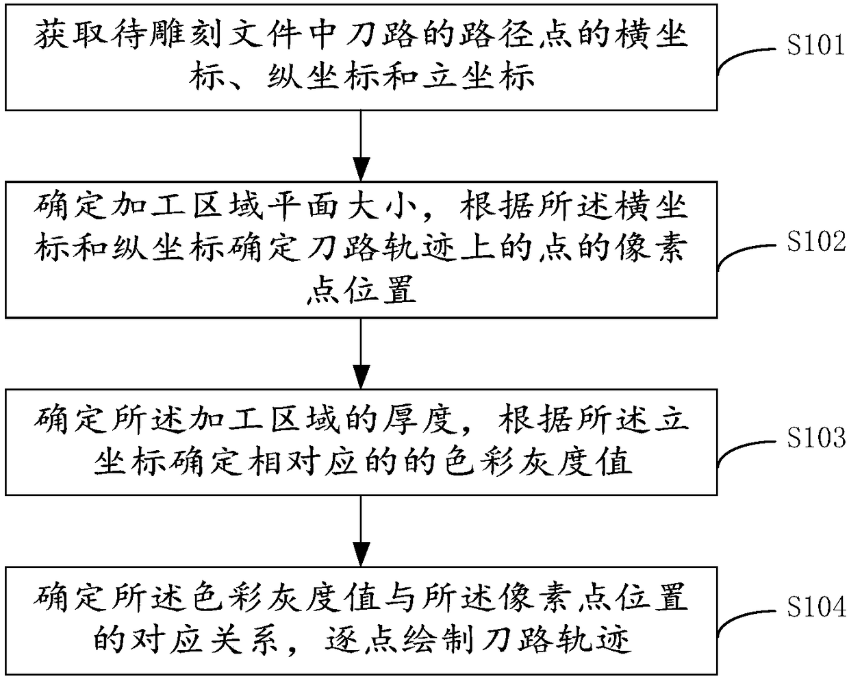
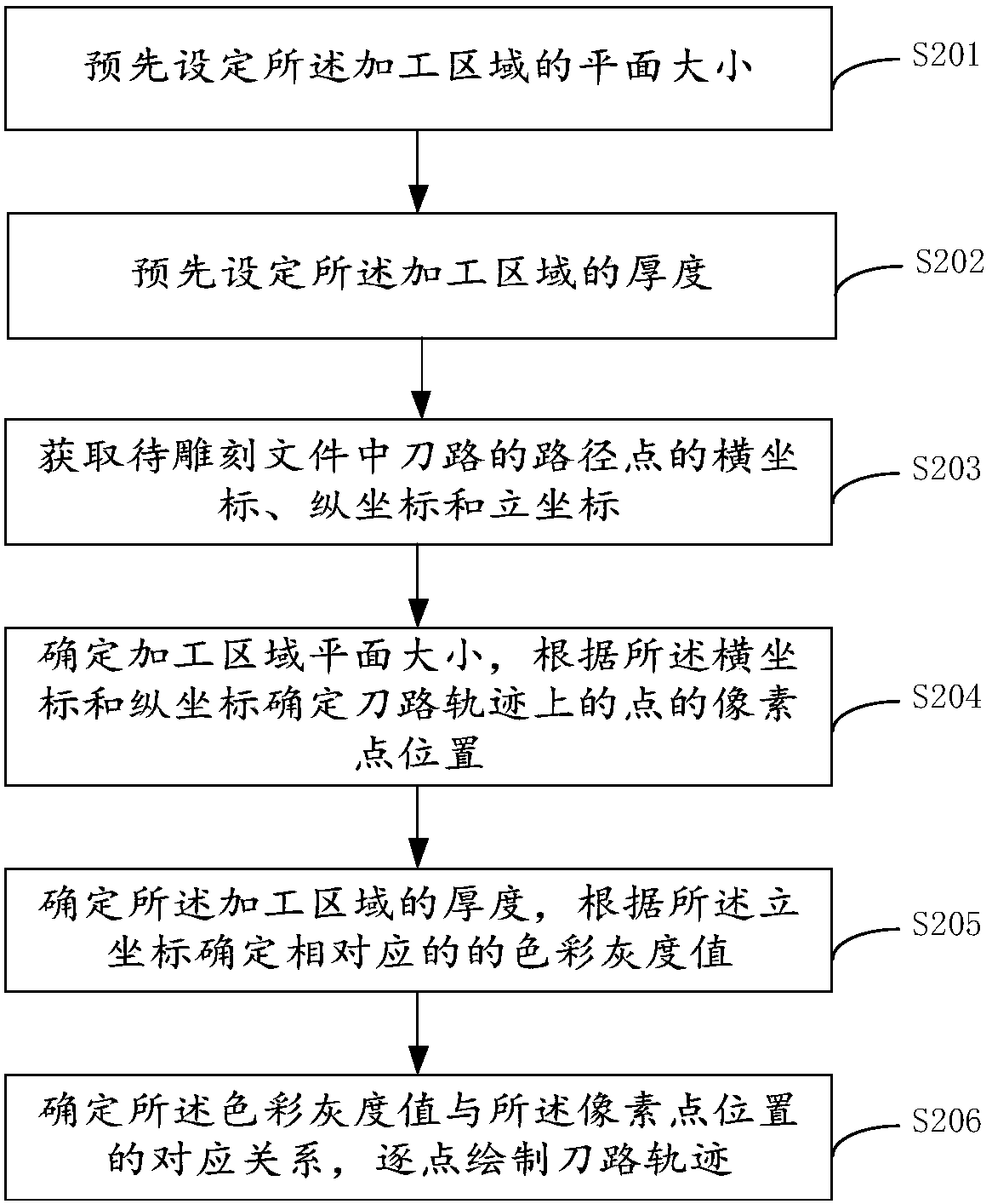
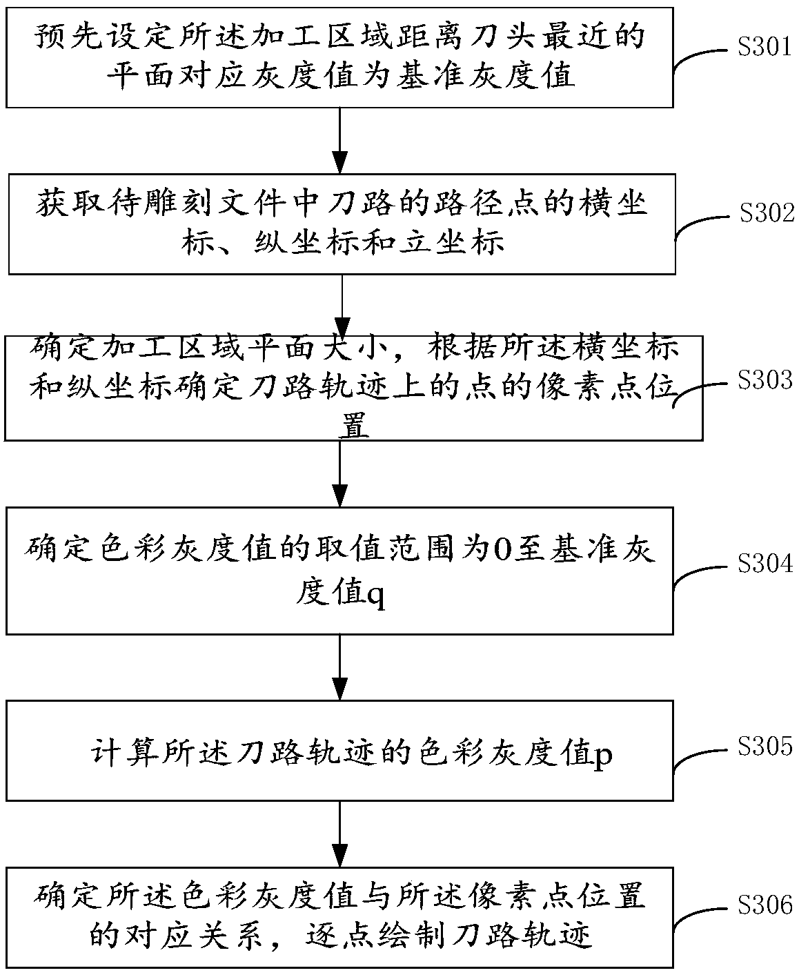
The invention provides a tool path reduction display method. The method comprises steps as follows: acquiring horizontal coordinates, longitudinal coordinates and vertical coordinates of path points of a tool path in a to-be-engraved file; determining the size of a to-be-processed area plane, and determining the pixel point positions of the tool path points according to the horizontal coordinates and the longitudinal coordinates; determining the thickness of the to-be-processed area and determining a color gray value of the tool path according to the vertical coordinates; determining a corresponding relation between the color gray value and the pixel point positions, and drawing the tool path point by point. Three-dimensional reconstruction is not required in the reduction display process of the tool path, then operation such as plane reconstruction, rendering and the like is also not required, the display method is simpler, the processing procedure is faster, and requirements for performance of processing equipment are reduced; meanwhile, the tool path is displayed in a mode of the color gray value, the specific condition of the tool path can be still known clearly, the display effect is better, and the tool path can be still displayed through reduction under the condition of lower performance of the processing equipment.

Description

technical field [0001] The invention relates to the technical field of engraving machines, in particular to a method and system for restoring and displaying tool path tracks and an engraving machine. Background technique [0002] The engraving machine can carve a corresponding pattern on the material to be processed according to a pattern to be engraved. During the simulation process of the processing file, you can use the tool path display function to observe whether the controller can correctly identify the instruction information in the processing file. , the machining process can be tracked and observed through the tool path display function. [0003] In the engraving industry, relief processing files are converted from relief grayscale images through related software. At present, most of the engraving and milling control systems that support the tool path drawing function use three-dimensional display technology to draw the tool path, so this puts forward higher requir...

Claims


Application Information

Patent Timeline
Patent Type & Authority Patents(China)
IPC IPC(8): G06F17/50B44B1/00
CPCB44B1/006B44B2700/04G06F30/17
Inventor 刘云涛方丽颖汪杰
Owner 刘云涛
Learn More