
Method for nondestructively detecting defects of high-precision elements

A high-precision, component-based technology, applied in the direction of optical testing flaws/defects, etc., can solve problems such as poor application of optical testing methods, low detection accuracy, and difficulty in achieving high-precision non-destructive testing, so as to improve acquisition speed and detection Efficiency, data accuracy, and high-precision non-destructive testing effects

Inactive Publication Date: 2016-04-13
UNIV OF SCI & TECH OF CHINA
View PDF5 Cites 3 Cited by
  • Summary
  • Abstract
  • Description
  • Claims
  • Application Information

AI Technical Summary

Problems solved by technology

For the detection of these high-precision non-transparent objects and internal defects, the traditional optical detection method is not very suitable, like the transmission grating can only observe the surface topography of a small field of view through the electron microscope, and the X-ray detection method based on X-ray absorption Although it can be applied to non-transparent objects, its detection accuracy is not high. There are many shortcomings in the ray detection of aircraft parts, and it is difficult to achieve the purpose of high-precision non-destructive testing.

Method used

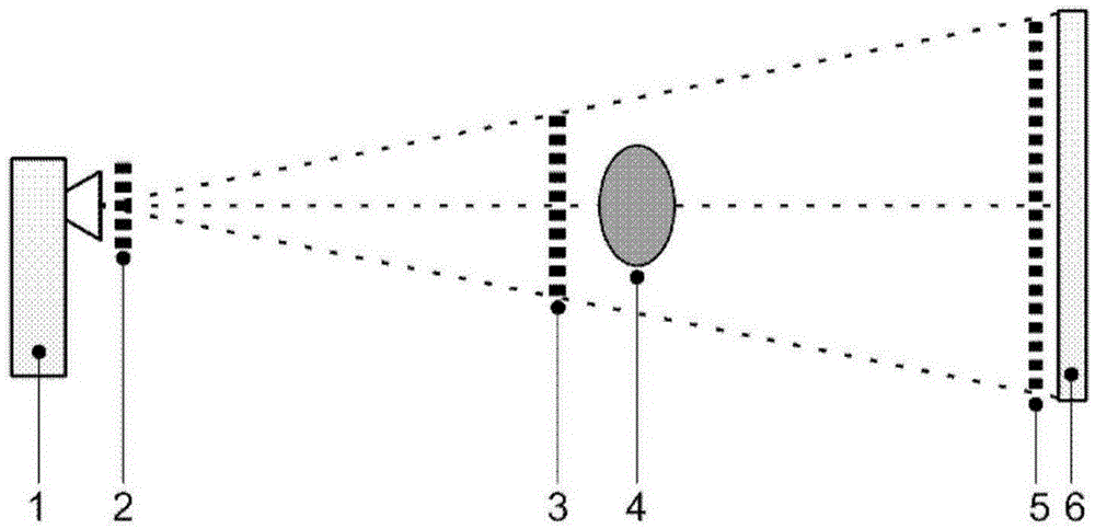
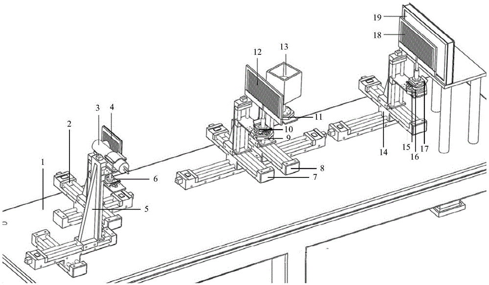

Image

  • Method for nondestructively detecting defects of high-precision elements
  • Method for nondestructively detecting defects of high-precision elements
  • Method for nondestructively detecting defects of high-precision elements

Examples


Embodiment Construction

[0024] The technical solutions in the embodiments of the present invention will be clearly and completely described below in conjunction with the accompanying drawings in the embodiments of the present invention. Obviously, the described embodiments are only some of the embodiments of the present invention, not all of them. Based on the embodiments of the present invention, all other embodiments obtained by persons of ordinary skill in the art without making creative efforts belong to the protection scope of the present invention.

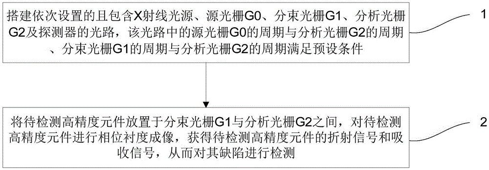
[0025] figure 1 It is a flow chart of a method for nondestructively detecting defects of high-precision components provided by an embodiment of the present invention. Such as figure 1 As shown, it mainly includes:

[0026] Step 1. Build an optical path that is set in sequence and includes the X-ray light source, source grating G0, beam splitting grating G1, analysis grating G2 and detector, the period of the source grating G0 and the period of th...


PUM


Abstract

The invention discloses a method for nondestructively detecting defects of high-precision elements. The method comprises the following steps: setting up a light path comprising an X-ray light source, a source grating G0, a beam-dividing grating G1, an analysis grating G2 and a detector which are sequentially arranged, wherein the period of the source grating G0 and the period of the beam-dividing grating G2 as well as the period of the beam-dividing grating G1 and the period of the analysis grating G2 in the light path meet preset conditions; placing the high-precision elements to be detected between the beam-dividing grating G1 and the analysis grating G2, carrying out phase-contrast imaging on the high-precision elements to be detected so as to obtain a refraction signal and an absorption signal of the high-precision elements to be detected, and thus detecting the defects of the high-precision elements. With the adoption of the method disclosed by the invention, small defects of the high-precision elements can be detected efficiently and the method is suitable for non-transparent objects.

Description

technical field [0001] The invention relates to the technical field of non-destructive testing, in particular to a method for non-destructive testing of high-precision component defects. Background technique [0002] Many precision components require extremely high uniformity or shape regularity as a guarantee of their own performance, such as flat glass, aluminum mirrors, gratings, etc. Flat glass is an important optical part, and its flatness will affect the direction of the optical axis of the optical system, thereby affecting the imaging quality; the aluminum reflector is formed by vacuum coating on the optical flat plate, and its reflection efficiency is directly related to the flatness. Flatness is also related to whether the image is distorted or ghosting occurs. [0003] For these transparent optical precision components, traditional optical inspection has better applicable methods, such as detecting flat glass with a float glass belt defect detector. In addition, ...

Claims


Application Information

Patent Timeline
Patent Type & Authority Applications(China)
IPC IPC(8): G01N21/95
CPCG01N21/95
Inventor 刘刚张灿王圣浩胡仁芳韩华杰侯双月陆亚林
Owner UNIV OF SCI & TECH OF CHINA
Learn More