Pumping reversing control method

A control method and pumping technology, applied in servo motors, mechanical equipment, fluid pressure actuating devices, etc., can solve the problems of load and flow gears, low reliability and inability to adapt to changes, etc., to achieve high reliability, The effect of improving reliability

Active Publication Date: 2019-07-23
ZOOMLION HEAVY IND CO LTD
View PDF5 Cites 0 Cited by
  • Summary
  • Abstract
  • Description
  • Claims
  • Application Information

AI Technical Summary

Problems solved by technology

Therefore, the above-mentioned pumping reversing control method cannot adapt to changing loads and flow gears, and the reliability is not strong

Method used


Image

  • Pumping reversing control method
  • Pumping reversing control method
  • Pumping reversing control method

Examples


Embodiment 2

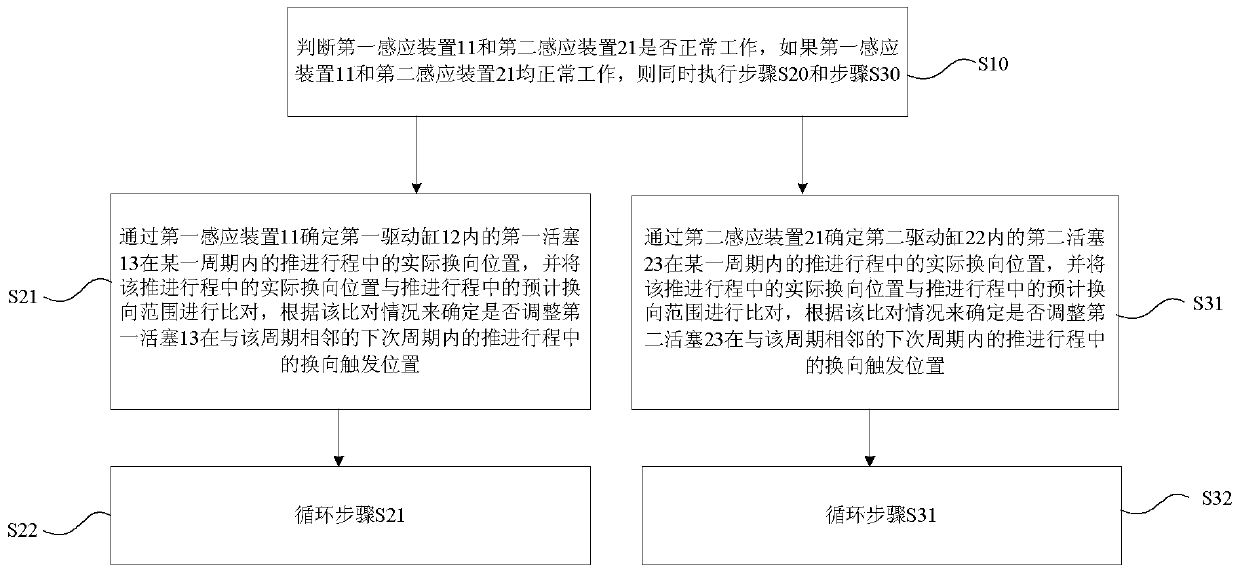
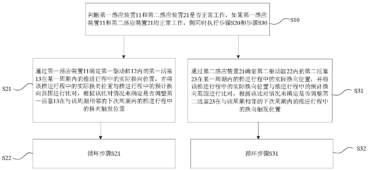
[0045] The pumping reversing control method of Embodiment 2 is also applied to the pumping device applied by the pumping reversing control method of Embodiment 1. The pumping reversing control method of Embodiment 2 includes Step S20 and Step S30, wherein the step S20 comprises step S21 and step S22, and step S30 comprises step S31 and step S32, and above-mentioned each step is as follows:

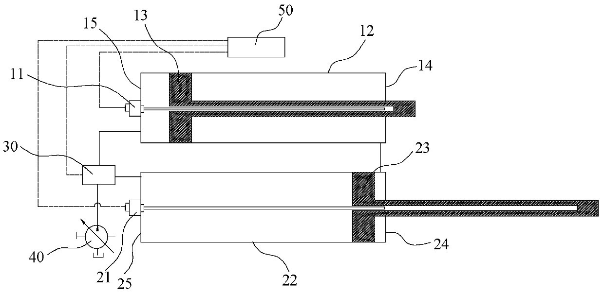
[0046] Step S21: Determine the actual reversing position of the first piston 13 in the first driving cylinder 12 in the retraction stroke within a certain cycle through the first sensing device 11, and compare the actual reversing position in the retraction stroke with The expected reversing range in the retraction stroke is compared, and it is determined whether to adjust the reversing trigger position of the first piston 13 in the retracting stroke in the adjacent next cycle according to the comparison. Step S22: loop through step S21.

[0047] Step S31: Determine the actual reversing p...


PUM


Abstract

The invention provides a pumping commutation control method comprising the following steps: step S10, simultaneously executing step S20 and step S30 if a first inductor and a second inductor can normally work; step S21: using the first inductor to determine a real commutation position in a propulsion stroke of a first piston in a first drive cylinder in certain period, comparing the real commutation position in the propulsion stroke with a predicted commutation scope in the propulsion stroke, and determining whether to adjust a commutation trigger position of the first piston in a propulsion stroke of the next period adjacent to the present period or not according to the comparison conditions; step S22: cycling the step S21; step S31: using the second inductor to determine a real commutation position of a second piston in a second drive cylinder in certain period in the propulsion stroke; step S32: cycling the step S31. The pumping commutation control method can adapt to changing loads, and is higher in reliability.

Description

technical field [0001] The present invention relates to the technical field of delivery devices, in particular to a pumping reversing control method. Background technique [0002] At present, concrete is mainly transported through a pumping device, which mainly includes a hydraulic pump, a reversing valve, and two hydraulic cylinders. The patent application with publication number 102410184A discloses a pumping reversing control method, device and system for a pumping device. Although the function of delivery can be realized, the above-mentioned pumping reversing control method is due to the fixed position of the reversing trigger , cannot well adapt to the change of the actual reversing displacement of the piston caused by the change of the load or flow gear, so it is impossible to avoid the situation that the piston in the hydraulic cylinder hits the two ends of the cylinder block, and it is impossible to ensure that the piston is pushed forward in place. In addition, whe...

Claims


Application Information

Patent Timeline
Patent Type & Authority Patents(China)
IPC IPC(8): F15B11/02F15B11/16
Inventor 李仁玉万梁李四中王帅
Owner ZOOMLION HEAVY IND CO LTD
Why Eureka
Try Eureka