Chute section

A technology of chute section and section, applied in the field of chute section, can solve the problems of crack formation, defects, high processing cost, etc.

Inactive Publication Date: 2007-06-06
CATERPILLAR INC
View PDF12 Cites 0 Cited by
  • Summary
  • Abstract
  • Description
  • Claims
  • Application Information

AI Technical Summary

Problems solved by technology

There are important disadvantages, mainly attributable to the many hitherto labor-intensive assembly operations and the high machining costs associated with welded joints, the risk of defects or cracks forming in welded joints, and the need for molds for rolled-formed parts high tooling cost
Nevertheless the second set of chute sections can still maintain its place in the market, because by replacing the worn parts the conveyor can be restored to full working capacity and result in a more favorable cost

Method used


Image

  • Chute section
  • Chute section
  • Chute section

Examples


Embodiment Construction

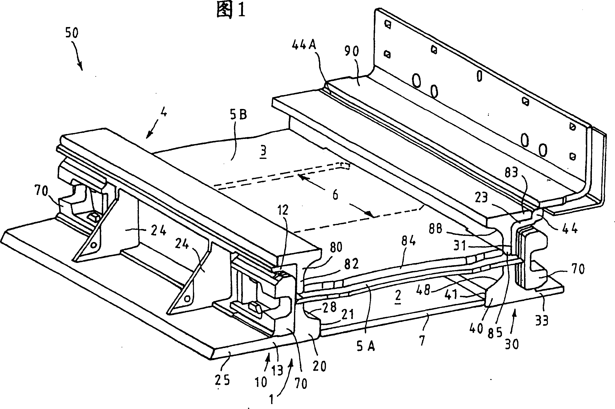
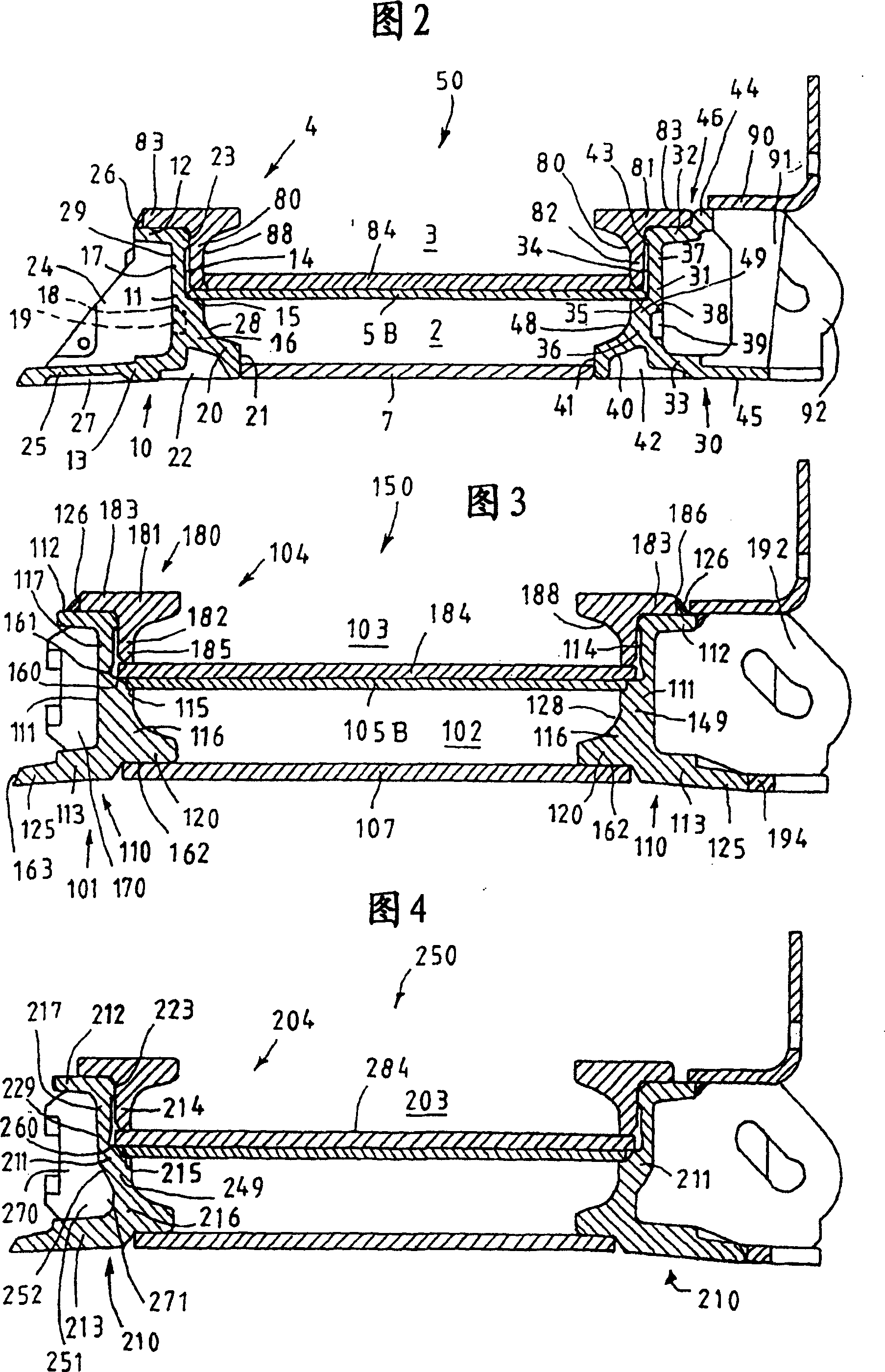
[0023] The chute section generally indicated by 50 in FIGS. 1 and 2 is an embodiment of a conveyor for underground longwall faces, which comprises a frame structure 1 directly forming the boundary of the lower working section 2 and a A replaceable or wearable groove 4 that constitutes the upper working section 3 is designed to be replaceable and bears on the frame structure 1 . The replaceable tank 4 shown in the assembled state can be lifted vertically from the frame structure 1 . The frame structure 1 of the chute section 50 has two differently designed asymmetric side frames 10, 30 composed of castings as important components, wherein the side frame 10 is arranged on the front wall side of the working face in the long wall working face conveyor, And the side frame 30 is provided on the filling side. The two side frames 10, 30 respectively have an intermediate flange 11, 31, a flange extension 12, 32 that protrudes outwards at the top and is cast on the intermediate flange ...


PUM


Abstract

The invention relates to a conveyor pan (150) for underground face and gate conveyors, with a bottom run (102) and a top run (103) for the guidance of a scraper of a scraper chain, with a frame work construction (101) which has side walls (110) comprising cast parts firmly joined to each other, with an intermediate flange (111) and an upper moulded flange lug (112) extending outwards from it and a lower moulded flange arm (113) as well as a moulded foot flange (120) extending inwards and bordering the bottom run partly to the side. In accordance with the present invention the cast part (110) has at least one step (115) on the inner wall (114) of the intermediate flange (111) for supporting and welding on a plate (105B) forming an intermediate plate, below which the intermediate arm (111) and the flange lug (120) form a profile strengthening (149), and above which the intermediate arm borders to the side an accepting space for the acceptance of an exchangeable tray (104) having rolled side profiles (180) welded to a conveyor base (184). The conveyor pan is made up of a few parts, which is in virtue of automatical assembly and jointing working procedure combination.

Description

technical field [0001] The invention relates to a chute section for longwall and level road conveyors in underground mines, which has asymmetrical side frames made of castings, which are connected to each other on an intermediate flange by a welded plate, the side frames Consists of a cast-on flange extension and a cast-in-bottom flange protruding outward from the middle flange and a cast-on lower flange protruding inward to form the lower working section for guiding the scraper chain scraper A bottom flange cast on the side boundary of the section section, on which a bottom plate is welded downwards to close the lower working section. Background technique [0002] Underground recovery equipment, such as underground mining, uses chain-type scraper conveyors with a large overall length, which consist of chute sections that are connected to each other in tension at the end sides. The connection of adjacent and mutually connected chute sections takes place, for example, by mea...

Claims


Application Information

Patent Timeline
IPC IPC(8): B65G19/28E21F13/00
CPCB65G19/28B65G19/285
Inventor 德克·福斯特尔格哈德·梅尔滕弗兰克·菲舍尔约尔格·维尔茨西格弗里德·施密特马丁·布罗萨特阿尔弗雷德·赫弗兰约翰·科布利阿利斯特·麦克安德鲁奥拉夫·洛斯布罗特
Owner CATERPILLAR INC
Why Eureka
Try Eureka