Brake device of vacuum pipeline wheel rail train

A vacuum pipeline and braking device technology, applied in pneumatic brakes, railway braking systems, hydrostatic brakes, etc., can solve the problems of high installation accuracy, affecting driving safety, brittle fracture of brake discs, etc., and achieve energy utilization. High, simple device structure, the effect of shortening the braking distance

Active Publication Date: 2016-04-13
上海洲跃生物科技有限公司
View PDF5 Cites 4 Cited by
  • Summary
  • Abstract
  • Description
  • Claims
  • Application Information

AI Technical Summary

Problems solved by technology

[0008] Air braking is the main means of emergency braking of high-speed trains in the atmospheric environment, and disc friction braking is the most important way of air braking. The disc braking method increases with the increase of train speed and kinetic energy. The heat energy generated during braking is also greatly increased. The huge braking heat load makes the brake disc prone to thermal fatigue damage, which is mainly manifested in mechanical damage, tissue deterioration and oxidative corrosion under the simultaneous action of alternating temperature and alternating thermal stress. In severe cases, radial cracks will be formed on the friction surface of the brake disc, which will easily lead to brittle fracture of the brake disc and affect driving safety. In addition, high-temperature creep, high-temperature oxidation and frictional heat on the surface of the brake disc will cause material softening and other problems.
[0009] Although the dynamic brake has high efficiency and is widely used in conventional braking, the design of the brake device is complicated, the installation precision is high, and there are many pipelines. Braking can only be used as an alternative means and not as the ultimate means of braking

Method used


Image

  • Brake device of vacuum pipeline wheel rail train
  • Brake device of vacuum pipeline wheel rail train

Examples


Embodiment Construction

[0030] The present invention will be described in further detail below in conjunction with the accompanying drawings.

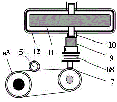
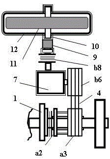
[0031] Such as figure 1 As shown, the device of the present invention at least includes: brake disc 1, clutch a2, pulley a3, transmission belt 4, tensioning mechanism 5, pulley b6, transmission gearbox 7, clutch b8, magnetic coupling 9, magnetic suspension bearing 10 , flywheel 11, vacuum chamber 12 and cooling device 13.

[0032] Assemble the brake disc 1 on the axle of the train, install the clutch a2 and the pulley a3 on the bearing of the axle, assemble the flywheel 11 in the vacuum chamber 12, install the transmission gearbox 7, the clutch b8, the magnetic coupling 9. The magnetic levitation bearing 10 and the vacuum chamber 12 are all fixed on the underframe of the train, and the pulley b6 is installed on the input shaft of the variable speed gearbox 7;

[0033] Connect one end of the clutch a2 with the pulley a3, and the other end engages with the bra...


PUM


Abstract

The invention discloses a brake device of a vacuum pipeline wheel rail train, which at least comprises a brake disc, a clutch a, a belt pulley a, a transmission belt, a tensioning mechanism, a belt pulley b, a speed change gear box, a clutch b, a magnetic coupling, a magnetic suspension bearing, a flywheel, a vacuum cavity and a cooling device, wherein the clutch a and the clutch b are automatically controlled by a computer; during braking, the clutch b is jointed with the magnetic coupling firstly, then the clutch a is combined with the brake disc, an axle drives the flywheel to rotate through the transmission belt and the speed change gear box, and the kinetic energy of the axle is changed to the kinetic energy of the flywheel; when the rotating speed of the flywheel reaches the maximum value, the clutch a is disconnected from the brake disc, the clutch b is disconnected from the magnetic coupling, and the flywheel still rotates at a high speed; and when the train starts, the clutch a is combined with the brake disc firstly, then the clutch b is jointed with the magnetic coupling, the kinetic energy of the flywheel is transferred to the axle through the gear box and the transmission belt, and thus the braking energy is changed to traction power.

Description

technical field [0001] The invention belongs to the technical field of braking of railway vehicles, and relates to a braking device of a vacuum pipeline wheel-rail train. Background technique [0002] For a train in an atmospheric environment, as the speed continues to increase, the interaction force between the train and the air becomes more and more intense, and the aerodynamic resistance, crosswind effect, cross-traffic effect, tunnel effect and aerodynamic noise are significantly enhanced. Taking a bullet train at a speed of 350 kilometers per hour as an example, the air resistance exceeds 90% of the total resistance of the train; due to the intensified vibration of the train in the air, the lateral and longitudinal sliding of the train on the wheel-rail is enhanced, resulting in the adhesion coefficient of the wheel-rail being reduced to that of a low-speed train about one-tenth of that of the train, which seriously affects the climbing and braking of the train; in addi...

Claims


Application Information

Patent Timeline
Patent Type & Authority Applications(China)
IPC IPC(8): B61H11/06B61H11/00B61C11/00
CPCB61C11/00B61H11/00B61H11/06
Inventor 李春洲
Owner 上海洲跃生物科技有限公司
Why Eureka
Try Eureka