A pcb soldering device

A technology of welding device and discharging device, which is applied in the direction of electric heating device, tin feeding device, welding equipment, etc., can solve the problems of difficult control of operation standardization, and achieve the effect of operation standardization and easy control, shortening length and reducing cost

Active Publication Date: 2018-05-18
深圳市全球威科技有限公司
View PDF7 Cites 0 Cited by
  • Summary
  • Abstract
  • Description
  • Claims
  • Application Information

AI Technical Summary

Problems solved by technology

[0003] The purpose of the present invention is to provide a pcb welding device to solve the technical problem that the operation standardization is not easy to control in the pcb welding process in the prior art

Method used


Image

  • A pcb soldering device
  • A pcb soldering device
  • A pcb soldering device

Examples


Embodiment 1

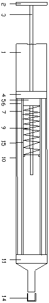
[0025] Such as figure 1 As shown, a pcb welding device includes a hollow tube 15, one end of the hollow tube 15 is sealed and connected with the discharge device 11, and the other end is sealed with the connection part 4, and the hollow tube 15 is connected with the discharge device 11 and the connection part 4 The sealing joints are all threaded connections, and the threaded connections are easy to disassemble. The discharge device 11 is funnel-shaped, and the tapered portion of the discharge device 11 is detachably provided with an end cap 14; the hollow tube 15 is provided with a piston 5, and a copper pipe 3 runs through the piston 5 along its axial direction. The copper tube 3 is connected to the piston in a sealed manner, the copper tube 3 passes through the connecting part 4, and can slide along the connecting part 4, the end of the copper tube 3 different from the piston 5 is provided with a handle 2; the hollow tube 15 is provided with a spring 9, The spring 9 is loc...

Embodiment 2

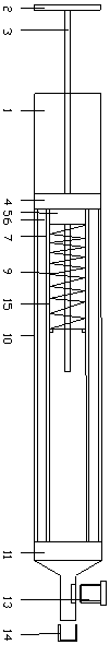
[0032] Such as figure 2 As shown, the middle part of the inner wall of the hollow tube 15 is provided with a boss, and the spring 9 is arranged between the piston 5 and the boss, which shortens the length of the spring 9 and reduces the cost. Others are identical to the structure described in Embodiment 1.

Embodiment 3

[0034] Such as image 3 As shown, the tapered portion of the discharge device 11 is provided with an adjustment device 13, and the size of the discharge port of the discharge device 11 is adjusted by the adjustment device 13 according to the size of the pad to control the flow rate of the liquid solder wire. Others are identical with the structure described in embodiment two.


PUM


Abstract

The invention discloses a pcb welding device which comprises a hollow pipe. One end of the hollow pipe is in sealing connection with a discharging device, and the other end of the hollow pipe is in sealing connection with a connecting part. The discharging pipe is in a funnel shape, and an end cover is detachably arranged on a conical part of the discharging device. A piston is arranged in the hollow pipe, and a copper pipe is arranged on the piston in a penetrating manner in the axis direction of the piston. The outer wall of the copper pipe is in sealing connection with the piston. The copper pipe penetrates the connecting part and can slide along a movable part, and a handle is arranged at the position, different from the end connected with the piston, of the copper pipe. A spring is arranged in the hollow pipe and located between the piston and the discharging device. The hollow pipe is sleeved with a shell, and the two ends of the shell are connected with the discharging device and the connecting part respectively. A heat insulation pad is arranged between the shell and the hollow pipe. A resistance wire is arranged between the heat insulation pad and the hollow pipe. A heat conduction insulation layer is arranged between the hollow pipe and the resistance wire. In the process of utilizing the device for pcb welding, operation standardability is easy to control, and welding quality is guaranteed.

Description

technical field [0001] The invention belongs to the technical field of pcb welding, and in particular relates to a pcb welding device. Background technique [0002] At present, when circuit developers use electric soldering irons to solder component pins, they usually use the right hand to hold the electric soldering iron and the left hand to hold the solder wire, and the electric soldering iron melts the solder wire for soldering. This manual pcb soldering method is difficult to control due to the standardization of operation , Different operators make the quality of welding vary, short circuit, short circuit, virtual welding and other problems often occur, the pass rate of the product is not high and the shape of the joint after welding is not beautiful. Contents of the invention [0003] The object of the present invention is to provide a pcb welding device to solve the technical problem in the prior art that the operation standardization is difficult to control during ...

Claims


Application Information

Patent Timeline
Patent Type & Authority Patents(China)
IPC IPC(8): B23K3/00B23K3/053B23K3/06B23K101/42
CPCB23K3/00B23K3/053B23K3/0623B23K2101/42
Inventor 周志近
Owner 深圳市全球威科技有限公司
Why Eureka
Try Eureka