
Zero-backlash low-noise transmission gear

A transmission gear, low-noise technology, applied in belts/chains/gears, components with teeth, portable lifting devices, etc., can solve pitting corrosion on tooth surfaces of enlarged gears, local plastic deformation of gluing, and difficult to eliminate gears Problems such as the backlash of the meshing parts of the gear teeth and the inability of the elastic gear to compensate radially can reduce the risk of failure, reduce the risk of broken teeth, and eliminate interference

Inactive Publication Date: 2016-03-30
HUNAN TONGSHENG JINGCHUAN TECH CO LTD
View PDF7 Cites 3 Cited by
  • Summary
  • Abstract
  • Description
  • Claims
  • Application Information

AI Technical Summary

Problems solved by technology

[0004] Although gear transmission has the above-mentioned characteristics, there are factors such as machining errors and assembly errors in the gear manufacturing process. In the design of gear transmission, it is necessary to leave a gap at the meshing position of the two gears of the transmission (called backlash in gear transmission). Backlash) to prevent the two transmission gears from being seized due to the interference caused by the above error; and this backlash will bring impact during the alternation process of the transmission gear meshing teeth, generate noise, and affect the transmission accuracy at the same time
[0005] In addition, since the size of the force direction of the gear teeth is obviously smaller than that of the gear body, the gear body is equivalent to a rigid body relative to the gear teeth, and the force of the gear teeth is equivalent to a cantilever beam. Stress concentration occurs at the joint part of the body, and the risk of gear teeth breaking
Moreover, since the gear transmission is a high-speed transmission with line contact, the stress on the contact part is very large. Due to the tooth profile and tooth direction error of the transmission gear, the contact part of the meshing teeth changes from line contact to point contact, so the stress on the contact part is even greater. Large, increasing the risk of pitting, gluing, and local plastic deformation on the gear tooth surface
[0006] Elastic gears are widely used in transmission gears, mainly to reduce noise by means of buffering, but the existing elastic gears cannot radially compensate, and it is difficult to eliminate the backlash of the meshing parts of the gear teeth; There is an obvious concentration point of tensile stress at the corner where the root circle meets; the meshing part of the gear teeth is basically point contact, the contact area is small, and the contact compressive stress on the tooth surface of the meshing part is large

Method used


Image

  • Zero-backlash low-noise transmission gear
  • Zero-backlash low-noise transmission gear
  • Zero-backlash low-noise transmission gear

Examples


Embodiment 1

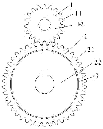
[0035] refer to figure 1 , this embodiment includes a driving wheel 1 and a driven wheel 2, the driving wheel 1 includes a driving wheel gear body 1-2 and a driving wheel gear tooth 1-1, and the driving wheel gear teeth 1-1 are evenly distributed on the driving wheel gear body 1 -2 on the peripheral edge; the driven wheel 2 includes a driven wheel gear body 2-2 and a driven wheel gear tooth 2-1, and the driven wheel gear tooth 2-1 is evenly distributed on the peripheral edge of the driven wheel gear body 2-2 The driven wheel gear tooth 2-1 meshes with the driving wheel gear tooth 1-1; the center of the driving wheel gear body 1-2 and the driven wheel gear body 2-2 are equipped with shaft holes; the driven wheel gear body 2-2 is close to The end face of the driven wheel gear tooth 2-1 root is provided with a circular arc groove, and the circular arc groove is composed of 6 segmented circular arc grooves 3 distributed along the circumference and concentric with equal diameters, ...

Embodiment 2

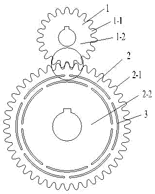
[0037] refer to figure 2 , image 3 , Figure 4 , the difference between this embodiment and Embodiment 1 is that: the end surface of the driven wheel gear body 2-2 close to the root of the driven wheel gear tooth 2-1 is provided with two circular arc grooves, which are respectively inner ring arc grooves and The arc grooves of the outer ring, the segments of the arc grooves of the inner ring and the segments of the arc grooves of the outer ring are staggered; the segmented arc grooves 3 are filled with plastic. All the other are with embodiment 1.

Embodiment 3

[0039] The difference between this embodiment and Embodiment 1 is that: the end surface of the driven wheel gear body 2-2 near the root of the driven wheel gear teeth 2-1 is provided with three circular arc grooves, which are respectively the first circular arc groove and the second circular arc groove. The second circle of arc grooves and the third circle of arc grooves, the segments of the first circle of arc grooves, the second circle of arc grooves and the third circle of arc grooves are staggered from each other; the segmental arc grooves 3 are filled with lead . All the other are with embodiment 1.


PUM


Abstract

The invention discloses a zero-backlash low-noise transmission gear. The zero-backlash low-noise transmission gear comprises a driving gear and a driven gear, wherein the driving gear comprises a driving gear body and driving gear teeth; the driving gear teeth are uniformly distributed on the circumferential edge of the driving gear body; the driven gear comprises a driven gear body and driven gear teeth; the driven gear teeth are uniformly distributed on the circumferential edge of the driven gear body; the driven gear teeth are meshed with the driving gear teeth; axle holes are respectively formed in the centers of the driving gear body and the driven gear body; the end face, close to the root parts of the driven gear teeth, of the driven gear body is provided with a ring arc-shaped groove; the ring arc-shaped groove consists at least two segmented arc-shaped grooves which are distributed along the circumference, equal in diameter and concentric; the segmented arc-shaped grooves are through grooves arranged along the axial direction of the gear. The zero-backlash low-noise transmission gear disclosed by the invention has the advantages of reducing the contact pressure stress of the tooth surfaces at the meshed position, reducing concentration of bending pull stress of the root parts of the gear teeth and improving the transmission precision.

Description

Technical field [0001] The invention involves the transmission gear, which specifically involves a zero -back low noise transmission gear. Background technique [0002] Gear transmission is the most widely used transmission form in mechanical transmission.The transmission gear refers to the use of the main and the motion of the main and from the moving gear to transmit power and movement, and use the wheel tooth to mesh of the two gears to transmit power and movement.The gear transmission is classified according to the relative position of the gear axis, which can be divided into parallel cylindrical gear transmission, intersecting cone gear transmission, and staggered spiral gear transmission. [0003] The characteristics of gear transmission are: stable transmission, accurate transmission ratio, reliable work, high efficiency, long life, large use power, speed, and size range. [0004] Although gear transmission has the characteristics of the above, there are factors such as pr...

Claims


Application Information

Patent Timeline
IPC IPC(8): F16H55/18
CPCF16H55/18
Inventor 吴治华
Owner HUNAN TONGSHENG JINGCHUAN TECH CO LTD
Learn More