
Circuit breaker

A circuit breaker and short-circuit protection technology, which is applied in the direction of protection switch operation/release mechanism, etc., can solve the problems of overlapping placement space, long operation time of B pole units, and affecting the reliability of circuit breakers, so as to achieve small overall size, shorten tripping time, etc. The effect of reducing time, improving reliability and stability

Active Publication Date: 2016-03-23
BEIJING PEOPLES ELECTRIC PLANT
View PDF4 Cites 2 Cited by
  • Summary
  • Abstract
  • Description
  • Claims
  • Application Information

AI Technical Summary

Problems solved by technology

exist Figure 7-8 In the shown circuit breaker, the placement space of the operating mechanism and the electromagnetic short-circuit protection mechanism overlap, which will result in that only the A and C pole units can be equipped with the electromagnetic short-circuit protection mechanism, while the B pole unit cannot be installed with the electromagnetic short-circuit protection mechanism
When the B-pole unit is short-circuited to ground, since the B-pole unit does not have an electromagnetic short-circuit protection mechanism, the action time of the B-pole unit will be relatively long, thus affecting the breaking performance and reliability of the circuit breaker
When the AB and BC poles are short-circuited, only one pole is equipped with an electromagnetic short-circuit protection mechanism, so only a single-layer protection can be formed. If the electromagnetic short-circuit protection mechanism is abnormal, the circuit cannot be cut off quickly, which affects the reliability of the circuit breaker.

Method used


Image

  • Circuit breaker
  • Circuit breaker
  • Circuit breaker

Examples


Embodiment Construction

[0020] Features and exemplary embodiments of various aspects of the invention will be described in detail below. In the following detailed description, numerous specific details are set forth in order to provide a thorough understanding of the present invention. It will be apparent, however, to one skilled in the art that the present invention may be practiced without some of these specific details. The following description of the embodiments is only to provide a better understanding of the present invention by showing examples of the present invention. The present invention is by no means limited to any specific configuration set forth below, but covers any modification, substitution and improvement of elements and components without departing from the spirit of the invention. In the drawings and the following description, well-known structures and techniques have not been shown in order to avoid unnecessarily obscuring the present invention.

[0021] In order to better un...


PUM


Abstract

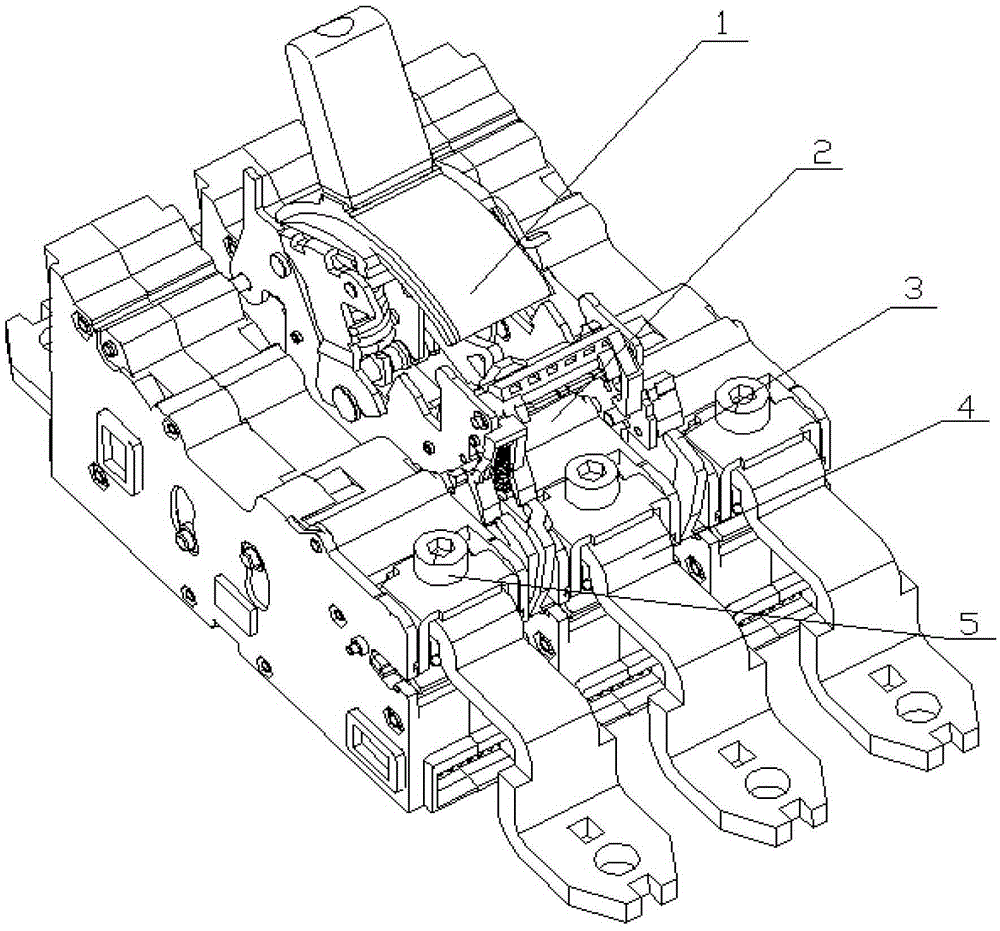
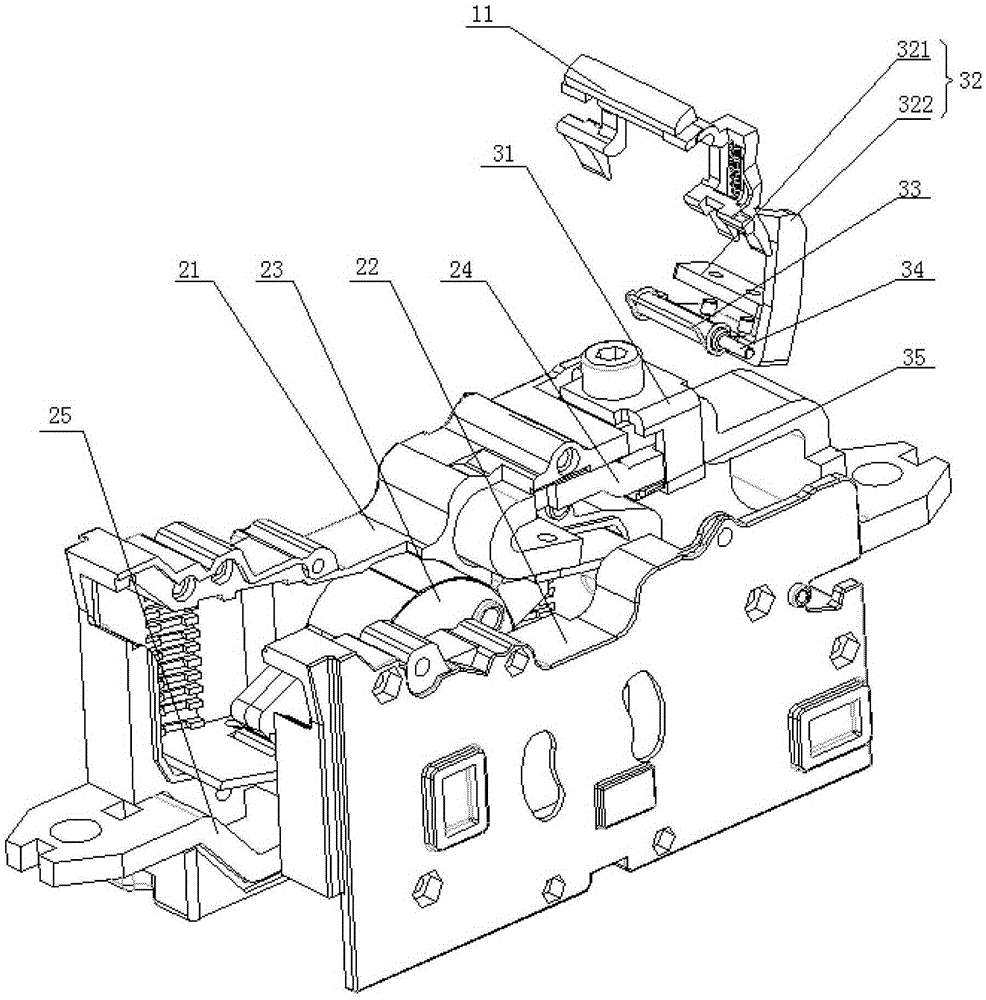
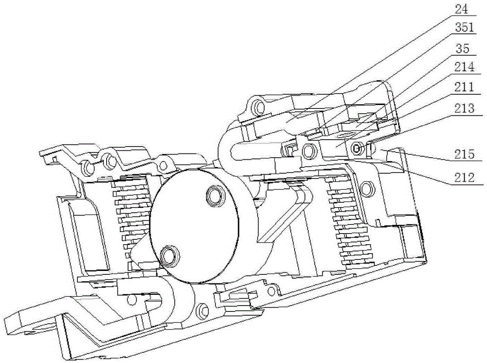
The invention discloses a circuit breaker. The circuit breaker comprises an operation mechanism, one or more one monopole units and one or more electromagnetic short circuit protection mechanisms. The operation mechanism is connected with a moving contact in each monopole unit so as to connection / disconnection of the moving contact with / from a static contact of each monopole unit, and each monopole unit is arranged to cooperate with one corresponding electromagnetic short circuit protection mechanism. Each electromagnetic short circuit protection mechanism comprises an iron core which is arranged above the static contact of the monopole unit arranged to cooperate with the electromagnetic short circuit protection mechanism; a lock catch brake device which is arranged below the static contact and is hinged with the inside of the monopole unit through a shaft; and an elastic element which is arranged between the lock catch brake device and the monopole unit. According to the invention, when fault currents flow through the static contacts, the iron cores are magnetized and generate electromagnetic attraction, when the electromagnetic attraction is greater than the counterforce of the elastic elements, and the lock catch brake devices rotate towards the directions of the iron cores so that lock catches in the operation mechanism brake, the moving contacts and the static contacts in the monopole units are disconnected, and the fault currents are cut off accordingly.

Description

technical field [0001] The invention relates to the field of low-voltage electrical appliances, in particular to a circuit breaker. Background technique [0002] The circuit breaker is an important electrical component in the field of low-voltage electrical appliances. As an electrical component to protect the low-voltage power distribution system, it can not only switch on and off the circuit under load, but also automatically switch on and off under short-circuit, overload, and low-voltage (loss of voltage) conditions. trip. The short-circuit protection device is an extremely important mechanism in the circuit breaker, because the operation time of the short-circuit protection device will directly affect the breaking capacity of the circuit breaker. [0003] Existing rotary double breakpoint molded case circuit breakers mainly include an operating mechanism, one or more unipolar units, and an electromagnet short-circuit protection device, wherein: each unipolar unit inclu...

Claims


Application Information

Patent Timeline
Patent Type & Authority Applications(China)
IPC IPC(8): H01H71/24
CPCH01H71/24
Inventor 南寅吴来顺刘万里李贤凯
Owner BEIJING PEOPLES ELECTRIC PLANT
Learn More