
Rolling bearing high-speed vibration testing method

A rolling bearing and vibration testing technology, which is applied in the direction of mechanical bearing testing, mechanical component testing, machine/structural component testing, etc., can solve problems such as poor vibration performance of bearings, existence of differences, and inability to characterize bearing vibration, etc., to reduce economic costs loss effect

Inactive Publication Date: 2016-03-23
HARBIN INST OF TECH +1
View PDF3 Cites 2 Cited by
  • Summary
  • Abstract
  • Description
  • Claims
  • Application Information

AI Technical Summary

Problems solved by technology

[0003] 1. There is a certain degree of generality in evaluating the vibration of the bearing by using the root mean square value alone. Even if the peak value is added as an auxiliary detection index, there will be differences in the evaluation of the vibration level of the bearing together.
[0004] 2. The vibration of bearings is different under different working conditions. For bearings with smaller sizes in the national standard, the higher speed used is from 2400r / min to 3600r / min, while the current speed of grinding high-speed electric spindles is as high as 60000r / min , the vibration behavior at high speed is different from that at low speed, so the measured value at low speed cannot represent the vibration at high speed, nor can it represent the vibration when the bearing is a part of the whole machine
The first problem is that the vibration performance of the same batch of bearings is different, and even the phenomenon of excessive vibration of the bearings occurs
The second problem is that the rotational speed of the standard bearing vibration measurement is low, while the rotational speed of the bearing is relatively high in the actual application process. The vibration behavior of the bearing is different at low speed and high speed, which results in good low-speed vibration performance and high-speed vibration performance. The problem of poor vibration performance of the bearing in case

Method used


Image

  • Rolling bearing high-speed vibration testing method
  • Rolling bearing high-speed vibration testing method
  • Rolling bearing high-speed vibration testing method

Examples


specific Embodiment approach 1

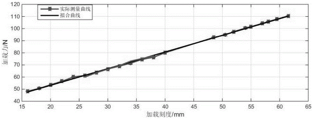
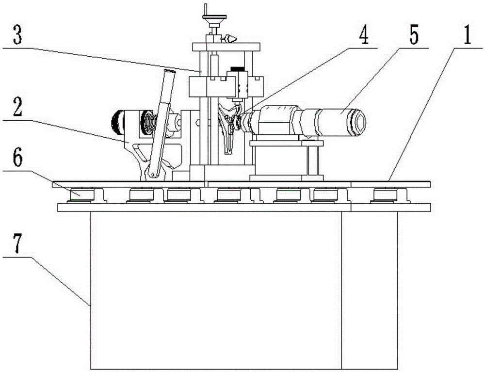
[0042] Specific implementation mode one: combine Figure 1 to Figure 22 To illustrate this embodiment, the method described in this embodiment includes the following steps:

[0043]Step 1: Build a high-speed vibration measuring instrument for rolling bearings: build a high-speed vibration measuring instrument for rolling bearings, build a high-speed vibration measuring instrument for rolling bearings according to the construction accuracy requirements of standard bearing measuring instruments for rolling bearings, and expand the speed of the standard vibration measuring instrument for rolling spindles on this basis range, using high-performance acceleration sensors to detect the vibration of bearings under high-speed working conditions; in this step, the speed of the rolling spindle standard vibration measuring instrument is expanded to a maximum of 60000r / min;

[0044] Step 2: Detect the high-speed vibration measuring instrument for rolling bearings: Detect the performance of...

Embodiment 1

[0058] Embodiment one: combined with attached Figure 16 This embodiment is described. This embodiment is to verify that the bearing has different vibration states at high speed and low speed, and it shows that the vibration evaluation of rolling bearings at high speed cannot use the vibration characterization at low speed. Select bearings numbered 03# and 15# in the above verification test. From the above verification test, it can be seen that the vibration of the 03# bearing is relatively large, while the vibration level of the 15# bearing is small. Perform high-speed vibration tests on a vibration measuring instrument. Depend on Figure 16 The root mean square of the bearing vibration signal changes with the speed can be clearly seen:

[0059] 1) The vibration of the bearing generally shows an increasing trend with the increase of the bearing speed, especially when the speed exceeds a certain level, the root mean square value will increase rapidly;

[0060] 2) The 3# bea...

Embodiment 2

[0061] Embodiment two: combined with attached Figure 17 Describe this embodiment, this embodiment is the vibration measurement of the test bearing 4 at different speeds, 6 sets are selected from the above-mentioned test bench verification test, respectively 03#, 06#, 08#, 16#, 11#, 15# #Bearing, carry out bearing vibration tests at different speeds on a high-speed bearing vibration measuring instrument, use the root mean square RMS to characterize the vibration of the bearing, and the analysis results are shown in the figure. The root mean square value reflects the overall energy of the vibration signal, and the larger the root mean square value, the greater the vibration. by attaching Figure 17 It can be seen that as the speed increases, the RMS values ​​of the six sets of bearings all increase, and the vibrations all increase.


PUM


Abstract

The invention relates to a high-speed vibration testing method, in particular, a rolling bearing high-speed vibration testing method. Existing bearing detection methods all adopt low-speed detection, while, the actual working states of bearings are high-speed states, and as a result, the current low-speed detection means cannot meet the requirements for mastering the actual performance of the bearings, and detection data cannot meet the requirements of actual work. The rolling bearing high-speed vibration testing method of the invention includes following five steps that: step One: a high-speed rolling bearing vibration tester is built; step Two: the high-speed rolling bearing vibration tester is detected; step Three: a frequency converter is debugged, and a loading force F is applied; step Four: a band-pass filter is debugged; and step Five: vibration is evaluated. The rolling bearing high-speed vibration testing method of the invention has the advantages of reasonable design, simple operation and accurate and reliable detection results. The operation process of the rolling bearing high-speed vibration testing method simulates the work mode of a bearing in high-speed operation. The rolling bearing high-speed vibration testing method of the invention is used for measuring various kinds of performance of rolling bearings in high-speed rotation.

Description

technical field [0001] The invention specifically relates to a high-speed vibration test method for a rolling bearing. Background technique [0002] In 1993, my country formulated the first bearing industry standard to regulate the vibration performance of bearings: "JB / T7047-93 Technical Conditions for Vibration Acceleration of Rolling Bearings and Deep Groove Ball Bearings", which were revised in 1999 and 2006 respectively. The standard standardizes the design, production and application of bearings, has a major and profound impact on improving the quality of bearings, and has important guiding significance for the activities of the bearing industry. However, the current bearing vibration detection standards, whether it is the national standard or the industry standard, still have insufficient evaluation of the vibration of high-speed bearings. The specific performance is as follows: [0003] 1. There is a certain generality in using the root mean square value alone to ev...

Claims


Application Information

Patent Timeline
Patent Type & Authority Applications(China)
IPC IPC(8): G01M13/04
CPCG01M13/045
Inventor 王黎钦侯萍萍古乐柏迎村雷军
Owner HARBIN INST OF TECH
Learn More