Improved thin film pneumatic control valve

A pneumatic control valve, an improved technology, applied in the direction of valve lift, valve device, valve details, etc., can solve the problems of valve core not closing properly, pressure difference not easy to be too large, valve and pipe elbow bursting, etc., to avoid swinging , to avoid discouragement, to facilitate the control effect

Active Publication Date: 2019-01-04
JIANGSU JULIANG AUTOMATIC CONTROL VALVE CO LTD
View PDF6 Cites 0 Cited by
  • Summary
  • Abstract
  • Description
  • Claims
  • Application Information

AI Technical Summary

Problems solved by technology

However, there is a defect of large unbalanced force when switching, which requires that the pressure difference is not too large during operation.
The reason is: in the steam pipeline, when the steam passes through the steam at the inlet and outlet of the single-seat pneumatic film regulating valve, there is a large pressure difference, the valve core will not close properly, resulting in inaccurate heating temperature control and affecting production quality.
[0003] Although the sleeve pneumatic film control valve and the double-seat pneumatic film control valve have small unbalanced force when switching, they are not affected by the steam pressure difference between the inlet and outlet of the valve, but the large leakage will affect the heating temperature control of the equipment during use. Accuracy
When the equipment needs to be cooled by water, steam leaks because the valve is not closed properly, which not only causes waste of steam, but also causes bursts of sound in the pipeline due to steam encountering cold water, and even causes the vibration of the pipeline to deviate from the original position, and the deviation of the pipeline will also cause Hazardous hazards of bursting valves and pipe elbows

Method used


Image

  • Improved thin film pneumatic control valve
  • Improved thin film pneumatic control valve

Examples


Embodiment Construction

[0018] The technical solutions of the present invention will be further specifically described below through the embodiments and in conjunction with the accompanying drawings.

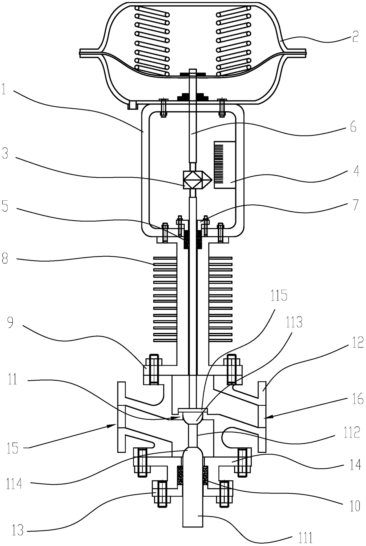
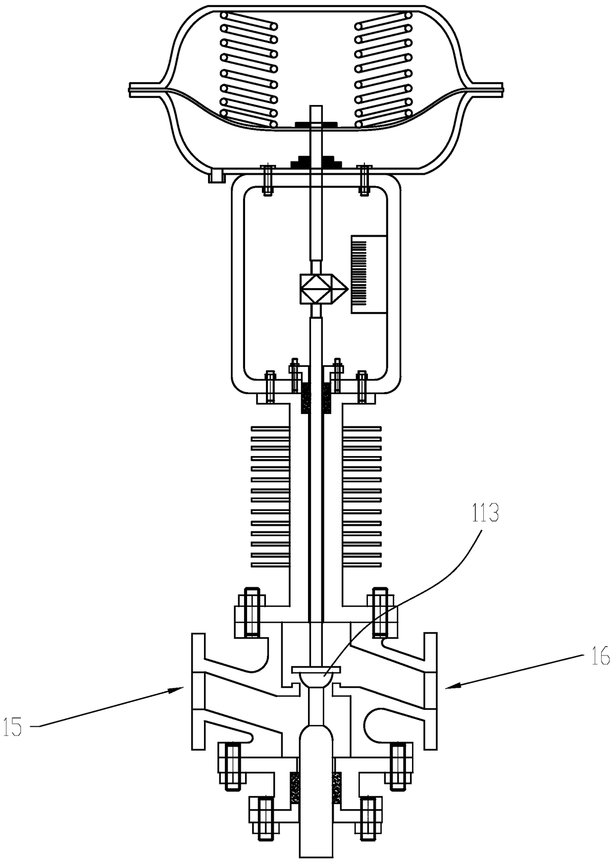
[0019] Embodiment: Improved thin-film pneumatic regulating valve, such as figure 1 As shown, it includes a valve seat 12 with an air inlet 15 and an air outlet 16, an air inlet passage and an air outlet passage arranged in the valve seat, a valve core 11 is arranged at the junction of the air inlet passage and the air outlet passage, The valve core 11 includes a core located at the inlet passage and the outlet passage and a lower valve stem fixed below the core, and the lower valve stem includes a positioning post 111 passing through the valve seat and a valve stem positioned at the valve seat. The connecting rod 112 in the seat, the lower end of the core is a hemispherical upper balance part 113, the upper end of the positioning column 111 is a hemispherical lower balance part 114, the upper balance p...


PUM


Abstract

The invention relates to an improved thin film pneumatic adjusting valve. The improved thin film pneumatic adjusting valve is characterized in that a valve element comprises a core located at an air inlet channel and an air outlet channel and a lower valve rod fixed below the core; the lower valve rod comprises a locating column penetrating out of a valve seat and a connecting rod located in the valve seat; a hemispherical upper balance part is arranged at the lower end of the core; a hemispherical lower balance part is arranged at the upper end of the locating column; the upper balance part and the lower balance part are arranged oppositely and connected with the connecting rod; and the size of the cross section of the locating column is larger than that of the cross section of the connecting rod. The improved thin film pneumatic adjusting valve has the beneficial effects that firstly, by means of the arrangement of the upper balance part and the lower balance part, smooth airflow is formed, and the valve element can be closed timely and accurately; secondly, the cross size of the connecting rod cannot be too large, the influence of steam impact force is avoided, it is further ensured that the valve element can be closed accurately, and air leaking is avoided; and thirdly, by means of the locating column, the valve element can be opened or closed stably, and swing is avoided.

Description

technical field [0001] The invention relates to an improved thin film pneumatic control valve. Background technique [0002] The single-seat pneumatic film regulating valve has the advantages of easy sealing and small leakage. It can well control the intake of steam when used in the steam inlet pipeline of equipment heated by steam. However, there is a defect of large unbalanced force when switching, which requires that the pressure difference is not too large during operation. The reason is: in the steam pipeline, when the steam passes through the steam at the inlet and outlet of the single-seat pneumatic film regulating valve, there is a large pressure difference, the valve core will not close properly, resulting in inaccurate heating temperature control and affecting production quality. [0003] Although the sleeve pneumatic film control valve and the double-seat pneumatic film control valve have small unbalanced force when switching, they are not affected by the steam p...

Claims


Application Information

Patent Timeline
Patent Type & Authority Patents(China)
IPC IPC(8): F16K1/00F16K1/32F16K1/36F16K49/00F16K47/02F16K37/00F16K41/02
CPCF16K1/00F16K1/32F16K1/36F16K37/0016F16K41/02F16K47/023F16K49/00
Inventor 马胜
Owner JIANGSU JULIANG AUTOMATIC CONTROL VALVE CO LTD
Why Eureka
Try Eureka