Hydraulic system of hydraulic self-moving type movable transformer train

A technology for shifting trains and hydraulic systems, applied in the direction of fluid pressure actuators, servo motors, servo motor components, etc., can solve the problems of pallet truck interference, pallet truck movement instability, and poor coordination of movements, etc., to improve flexibility , improve simultaneity, reduce the effect of quantity

Active Publication Date: 2016-03-16
BEIJING TIANMA INTELLIGENT CONTROL TECH CO LTD
View PDF6 Cites 1 Cited by
  • Summary
  • Abstract
  • Description
  • Claims
  • Application Information

AI Technical Summary

Problems solved by technology

The traditional hydraulic self-moving train hydraulic system is mainly controlled by a group of electro-hydraulic control reversing valves, which are installed in the end bracket. However, because the equipment train is too long, the length is generally between 100 and 200 meters. When a group of electro-hydraulic control and electro-hydraulic control reversing valves are used for control, the connecting pipeline from the outlet of the electro-hydraulic control reversing valve to the pallet car is too long. As a result, when the trolley is supplied with liquid and moves at the same time, the system requires a large amount of liquid. Due to the flow resistance loss of the long pipeline, the coordination of the movements between the trolleys is likely to be poor, and the staggered actions will cause the movement of the trolley to be unstable. The stability and responsiveness of the movement are greatly affected; at the same time, there is no selectivity for the control of the trolley, which leads to excessive interference between the movement of the trolley

Method used


Image

  • Hydraulic system of hydraulic self-moving type movable transformer train
  • Hydraulic system of hydraulic self-moving type movable transformer train
  • Hydraulic system of hydraulic self-moving type movable transformer train

Examples


Embodiment Construction

[0024] The present invention will be further described in detail below in terms of specific embodiments in conjunction with the accompanying drawings.

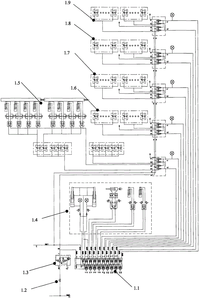
[0025] See attached figure 1 , which describes the schematic diagram of the overall system of the hydraulic self-moving shift train that controls the hydraulic control reversing valve through the hydraulic control port to realize partition control in the present invention; the self-moving shift train follows the layout of the hydraulic control reversing valve for partition control , by controlling the control port of the hydraulic control reversing valve separately to realize the group lifting and lowering action of the shifting train; the high-pressure pipeline P pipe is the main inlet pipeline, which is respectively connected with the main inlet P port of the hydraulic control reversing valve of each zone ;The low-pressure pipeline R pipe is the main liquid return pipe, which is respectively connected with the main liquid re...


PUM


Abstract

A hydraulic system of a hydraulic self-moving type movable transformer train breaks through a traditional mode that an end support and a single set of electro-hydraulic control reversing valves control a support and a group train simultaneously, and the thinking that one set of electro-hydraulic control reversing valves and multiple sets of hydraulic control reversing valves are adopted for controlling in a grouping and partitioning mode. The hydraulic system comprises the electro-hydraulic control reversing valves; part of function ports of the electro-hydraulic control reversing valves are used for controlling related actions of the end support, such as lifting of a stand column, stretching and contracting of a balanced oil cylinder and a pushing oil cylinder and other actions; the other function ports of the electro-hydraulic control reversing valves are used for being communicated with control ports of the hydraulic control reversing valves in the partitions to achieve the reversing action of the hydraulic control reversing valves; each hydraulic control reversing valve is provided with two control ports k1 and k2; when the control ports k1 are at high pressure, an A1 port and an A2 port of the hydraulic control reversing valves work and plate trailers descend; when the control ports k2 are at high pressure, an A3 port and an A4 port of the hydraulic control reversing valves work and the plate trailers ascend; each set of hydraulic control reversing valves are arranged in the middle of the corresponding partition of the plate trailer, and are used for controlling the ascending and descending actions of the plate trailers inside the left end partition and the right end partition.

Description

technical field [0001] The invention relates to a hydraulic self-moving train hydraulic system, in particular to the field of down-trough transport equipment in mines. Background technique [0002] With the development of coal mining technology, self-moving tails of belt conveyors with various forms and functions are widely used in fully mechanized mining faces of coal mines. At present, modern mines with tens of millions of tons have good site conditions, large coal storage capacity, and flat coal seams, which can carry out high-power, high-efficiency modern coal mining operations. The speed is fast, so it is required that the trough loader, belt conveyor and equipment train have a fast translation function, and the self-moving tail connected in the middle is the key. [0003] In the track lane of fully-mechanized coal mining face, the emulsion pump station, liquid tank, transformer, switch and other equipment are all fixed on the flatbed truck, and the flatbed trucks are ...

Claims


Application Information

Patent Timeline
Patent Type & Authority Applications(China)
IPC IPC(8): F15B13/02F15B11/00
Inventor 向虎韦文术王伟周如林刘晓萌苏哲李然
Owner BEIJING TIANMA INTELLIGENT CONTROL TECH CO LTD
Why Eureka
Try Eureka