
Low-cost speed regulation, parking and anti-slip equipment

A technology of parking equipment and equipment, which is applied in the direction of railway car body parts, track brakes, transportation and packaging, etc., can solve the problems of unreasonable design, underutilization, high manufacturing cost, etc., and achieve little increase in cost, cost reduction, and saving Effective at a considerable cost

Inactive Publication Date: 2016-03-16
董晓涵
View PDF0 Cites 0 Cited by
  • Summary
  • Abstract
  • Description
  • Claims
  • Application Information

AI Technical Summary

Problems solved by technology

[0002] Existing speed control equipment such as retarders for interval braking and purpose braking at the head of the railway hump marshalling station, and parking equipment for the tail of the railway hump marshalling station, as well as anti-slip equipment for railway arrival and departure line anti-slip , the distance between these equipment sections is 1.2 meters, and these equipments are generally composed of N sections or N sections + N sections or N sections + N sections + N sections, or other combinations, such as N sections + (N+1) section or N section + (N+2) section, etc.; N is generally 4 or 6 or 7, N can also be 3 or 5 or 8 or 9, N can also be other positive integers; these devices All have brake rails. Except for the brake rails and control parts among their main parts, most of the other parts of these devices are repeated between the nodes, which makes the manufacturing cost of these devices higher.
[0003] It is used for the parking equipment at the tail of the railway hump marshalling station, and the anti-slip equipment for the arrival and departure line of the railway only brakes the inner side of the wheel. The brake rails they use are 50 rails, and the distance between the nodes is 1.2 meters, the small capacity hump used for purpose braking / interval braking also only brakes the inner side of the wheel, the brake rails they use are 50 rails, and the distance between nodes is 1.2 meters, these designs are not reasonable , one is that the distance between the joints is small, the stiffness and strength of the brake rail are not fully exerted and waste materials, so that the braking ability of the equipment cannot be fully exerted, and the other is that the distance between the joints is too small, There are too many sections of each piece of equipment, and the cost is too high. It is entirely possible to reduce the number of sections of equipment by increasing the rigidity and strength of the brake rail, and increasing the distance between sections.
[0004] The speed regulating equipment used for head interval braking and purpose braking of railway hump marshalling stations, such as retarders, uses 60 rails for braking rails, and the distance between nodes is 1.2 meters. These designs are also unreasonable. , one is that the distance between the joints is small, the stiffness and strength of the brake rail are not fully exerted and waste materials, so that the braking ability of the equipment cannot be fully exerted, and the other is that the distance between the joints is too small, There are too many sections of each piece of equipment, and the cost is too high. It is entirely possible to reduce the number of sections of equipment by increasing the rigidity and strength of the brake rail, and increasing the distance between sections.

Method used


Image

  • Low-cost speed regulation, parking and anti-slip equipment
  • Low-cost speed regulation, parking and anti-slip equipment
  • Low-cost speed regulation, parking and anti-slip equipment

Examples


Embodiment Construction

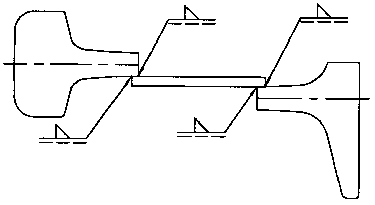
[0023] figure 1 What is shown is that a rail is divided into upper and lower parts from the waist part, the upper part and the lower part are separated by a certain distance in translation, and then the upper part and the lower part are connected by welding or riveting or other methods with steel plates, and the overrun part is removed.

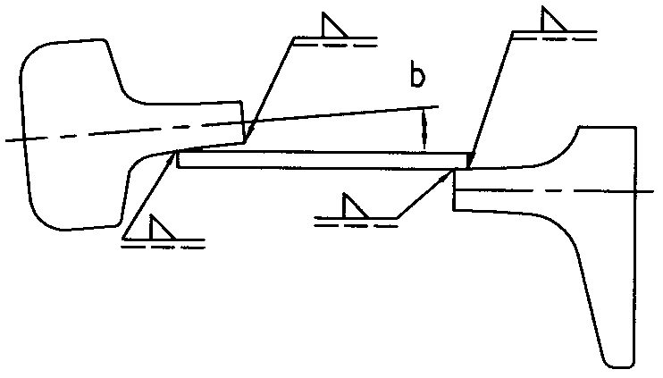
[0024] figure 2 What is shown is that a rail is divided into upper and lower parts from the waist part, and the upper part and the lower part are separated by a certain distance, and then the upper part and the lower part are connected by welding or riveting or other methods with steel plates. The overrun part is removed, and the head of the rail According to the need to deflect a certain angle downward, the angle size can be between 0-10 degrees or greater, preferably between 1.5-5 degrees.

[0025] image 3 What is shown is that a rail is divided into upper and lower parts from the waist, and after the upper part and the lower part are ...


PUM


Abstract

The invention relates to low-cost speed regulation, parking and anti-slip equipment. The low-cost speed regulation, parking and anti-slip equipment is characterized in that the pitch of the equipment is larger than 1.2 m, and the severity and the intensity of a brake rail are improved; as the pitch is increased, the pitch number of the equipment can be decreased, and therefore the cost of the equipment is reduced; due to the problem of ultralimit, an ultralimit part on one side of the bottom of the brake rail needs to be planed; as a steel rail is difficult to cut, the problem can be solved by an improved rail and the special brake rail; and the improved rail serves as the brake rail, planing is changed into cutting and welding, materials can be sufficiently used, and the intensity and the severity of the brake rail can be substantially improved.

Description

Technical field [0001] The present invention relates to a class of railway equipment, such as speed regulating equipment used in the field of railway equipment, especially speed regulating equipment used for interval braking and purpose braking at the head of a railway hump marshalling station, and used for parking at the tail of a railway hump marshalling station The equipment, as well as the anti-slip equipment for the arrival and departure lines of the railway, can also be used for other speed regulation, parking, and anti-slip equipment in the field of railway equipment. technical background [0002] Existing speed control equipment such as retarders for interval braking and purpose braking at the head of the railway hump marshalling station, and parking equipment for the tail of the railway hump marshalling station, as well as anti-slip equipment for railway arrival and departure line anti-slip , the distance between these equipment sections is 1.2 meters, and these equ...

Claims


Application Information

Patent Timeline
Patent Type & Authority Applications(China)
IPC IPC(8): B61K7/02
Inventor 董建平张志华董晓涵董晓雨
Owner 董晓涵
Learn More