
Friction welding phase control method

A phase control and friction welding technology, which is applied in welding equipment, manufacturing tools, non-electric welding equipment, etc., can solve the problems of poor phase control accuracy and achieve the effect of ensuring welding quality, overcoming mechanical shock and prolonging service life

Inactive Publication Date: 2017-07-25
NORTHWESTERN POLYTECHNICAL UNIV
View PDF7 Cites 0 Cited by
  • Summary
  • Abstract
  • Description
  • Claims
  • Application Information

AI Technical Summary

Problems solved by technology

[0006] In order to overcome the deficiency of poor phase control accuracy of existing friction welding phase control methods, the present invention provides a friction welding phase control method

Method used


Image

  • Friction welding phase control method

Examples


Embodiment Construction

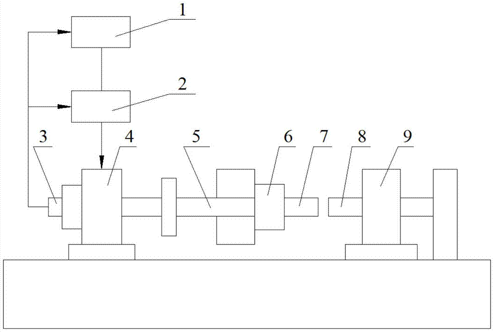
[0016] refer to figure 1 . The specific steps of the friction welding phase control method of the present invention are as follows:

[0017] The computer 1 detects the angular velocity value and angle value of the workpiece 7 at the rotating end through the photoelectric encoder 3. In the phase positioning control stage, the computer 1 outputs the torque value according to the angular acceleration, angular velocity and phase angle of the workpiece 7 at the rotating end and the change rule , flexibly adjust the output current of the DC amplifier 2, drive the DC motor 4 to rotate, control the angular acceleration, angular velocity and phase angle of the workpiece 7 at the rotating end, so that the angular acceleration of the workpiece 7 at the rotating end has no sudden change, the angular velocity decreases to zero smoothly, and the angle Reach the set value to achieve the purpose of precise phase positioning between the workpiece 7 at the rotating end and the workpiece 8 at t...


PUM


Abstract

The invention discloses a friction welding phase control method which is used for solving the technical problem that the phase control accuracy obtained through an existing friction welding phase control method is poor. According to the technical scheme, the method includes the steps that the angular speed value and the angle value of a rotating-end workpiece are directly detected through a computer; in the phase locating control stage, the computer outputs the torque value according to the values and the change rules of the angular acceleration, the angular speed and the phase angle of the rotating-end workpiece; and the output current of a direct-current amplifier is flexibly adjusted, so that a direct-current motor is driven to rotate, the angular acceleration, the angular speed and the phase angle of the rotating-end workpiece are controlled, the angular acceleration of the rotating-end workpiece is free of sudden changes, the angular speed of the rotating-end workpiece is stably reduced to zero, the angle of the rotating-end workpiece reaches the set value, and therefore the purpose of accurate phase localization between the rotating-end workpiece and a moving-end workpiece is achieved. By the adoption of the method, mechanical impact, current impact and forcible torsion can be effectively overcome, and the phase control accuracy of an actual welding piece is improved.

Description

technical field [0001] The invention relates to a phase control method, in particular to a friction welding phase control method. Background technique [0002] Most of the existing friction welding phase control is based on the precise control of the braking point of the rotating end, and two specific methods are derived: electronic DC braking positioning, electronic mechanical forced positioning, and the "homeopathic" phase control method of the mobile end. [0003] Document 1 "Phase Friction Welding Process and Equipment Research Wang Xingbin's Eighth National Welding Conference Proceedings Volume II 2-280" discloses an electronic DC braking positioning method. When the spindle angular velocity drops to a predetermined value, the control The inverter issues a command to start the phase detection device, and the detection system accurately measures the relative position of the two workpieces. When the phases of the two workpieces are aligned, the frequency converter perform...

Claims


Application Information

Patent Timeline
Patent Type & Authority Patents(China)
IPC IPC(8): B23K20/12
CPCB23K20/124
Inventor 杜随更郭扭权冬王松林
Owner NORTHWESTERN POLYTECHNICAL UNIV
Learn More