
A device for friction welding phase control

A phase control and friction welding technology, applied in the field of friction welding, can solve the problems of easy damage to the motor and affect the welding quality, achieve uniform deceleration, improve stability, and avoid impact.

Active Publication Date: 2017-03-22
LANZHOU UNIVERSITY OF TECHNOLOGY
View PDF5 Cites 0 Cited by
  • Summary
  • Abstract
  • Description
  • Claims
  • Application Information

AI Technical Summary

Problems solved by technology

[0004] In order to solve the problem that the motor is easily damaged and the welding quality is affected during the processing of the anode conductive device with large cross-section and large inertia due to the friction welding electronic mechanical forced positioning method, the present invention proposes a device for friction welding phase control , in order to be able to control the phase of the anode conductive device with large cross-section and large inertia during the friction welding process

Method used


Image

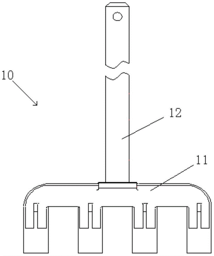
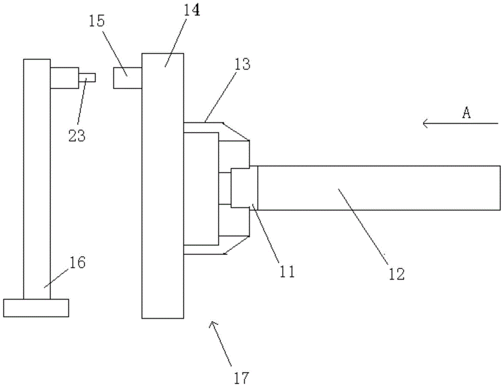
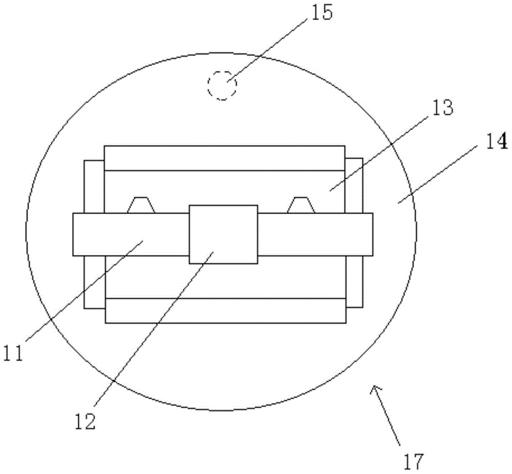
  • A device for friction welding phase control
  • A device for friction welding phase control
  • A device for friction welding phase control

Examples


Embodiment 1

[0029] Such as image 3 As shown, the device for friction welding phase control in this embodiment includes a control unit 20, a positioning unit 22, a positioning position unit 23, and a steel jaw clamp spindle motor 21. The control unit 20 is connected to the positioning unit 22 for sending positioning instructions to the positioning unit 22. The positioning unit 22 is respectively connected with the control unit 20 and the steel jaw clamp spindle motor 21 for controlling the steel jaw clamp spindle motor 21. For example, the positioning unit 22 controls the torque and the torque of the steel jaw clamp spindle motor 21 with output torque and speed signals. Rotation speed; the positioning unit 22 is also connected to the positioning unit 23, the positioning unit 23 periodically feedbacks a signal to the positioning unit 22, for example, every time the steel claw 11 rotates one revolution, the positioning unit 23 feedbacks a signal to the positioning unit 22; After receiving th...

Embodiment 2

[0036] Such as Figure 5 As shown, the device for friction welding phase control in this embodiment further includes a steel claw information unit 24 and an aluminum guide rod information unit 25.

[0037] The steel claw information unit 24 is respectively connected to the control unit 20 and the rear end of the reducer of the steel claw clamp spindle motor 21. The steel claw information unit 24 is used to collect the current position and speed information of the steel claw 11 and feed the information back to the control unit 20 , The control unit 20 calculates the number of turns of the steel claw 11 and the specific angle of the current circle where the steel claw 11 is located according to the position and speed information of the steel claw 11, so the control unit 20 first detects the steel before sending the positioning instruction to the positioning unit 22 The position information of the claw 11 to ensure that the steel claw 11 is in the same position before sending the pos...

Embodiment 3

[0040] Such as Image 6 As shown, the device for friction welding phase control in this embodiment further includes a speed feedback unit 26, which is respectively connected to the positioning unit 22 and the front end of the speed reducer of the steel jaw clamp spindle motor 21. The speed feedback unit 26 is used to collect the output speed of the positioning unit 22 and feedback the speed information to the positioning unit 22, so the speed feedback unit 26 and the positioning unit 22 construct a speed feedback closed loop, which improves the output accuracy of the positioning unit 22 and can assist in improving control. The positioning accuracy of the steel jaw clamp spindle motor 21. Among them, the speed feedback unit 26 is an incremental encoder.

[0041] The phase control accuracy of the anode conductive device obtained by using the present invention can be verified by the following measurement experiments:

[0042] 1. The experiment object is: when the aluminum guide rod ...


PUM


Abstract

The invention belongs to the technical field of friction welding, and provides a device for friction welding phase control to solve the problems that a motor is easy to damage and the welding quality is influenced occurring in processing of a positive-pole conductive device with a large section and a large inertia in a friction welding electronic machinery constrainedly positioning mode. The device comprises a control unit, a positioning unit and a spindle motor for a steel claw fixture. The positioning unit is connected with the control unit and the spindle motor for the steel claw fixture respectively. The control unit is used for sending a positioning instruction to the positioning unit, and the positioning unit controls the rotating speed of the spindle motor of the steel claw fixture to be in zero and finish the phase control at the same time once receiving the positioning instruction sent by the control unit. The device for friction welding phase control applies to the fast phase control of the positive-pole conductive device with the large section and the large inertia, the positioning time is smaller than 6 seconds, and the absolute value of the phase control error is smaller than 1 degree.

Description

Technical field [0001] The invention belongs to the technical field of friction welding, and particularly relates to a device for phase control of friction welding. Background technique [0002] Friction welding usually refers to the relatively high-speed movement of the joint surface of the same or dissimilar metals through a motor and hydraulic drive, and the pressure is applied after the joint surface reaches a plastic state due to friction and heat, and then quickly brakes, relying on inertial braking to achieve The welded metal is connected reliably. When the metal to be welded is a workpiece with a square structure, there are strict requirements on the positioning angle of the workpiece during the friction welding process, which involves phase control. At present, electronic mechanical forced positioning is usually used to control the phase of the square workpiece to be welded. Electronic mechanical forced positioning is to use a clamping block to block the motor shaft whe...

Claims


Application Information

Patent Timeline
Patent Type & Authority Patents(China)
IPC IPC(8): B23K20/12B23K20/227B23K103/20
CPCB23K20/123B23K20/2275B23K2103/20
Inventor 冯小林毛海杰刘满强芮执元辛舟李鄂民罗德春张昌青刘朝荣陈辉裴喜平张玮于振燕李经纬
Owner LANZHOU UNIVERSITY OF TECHNOLOGY
Learn More