Eureka AIR delivers breakthrough ideas for toughest innovation challenges, trusted by R&D personnel around the world.

Novel dynamic separation sieve

A separation screen and dynamic technology, applied in the direction of solid separation, filter screen, grid, etc., can solve the problems of destructive ground infrastructure, affecting screening efficiency, affecting normal operation, etc., to achieve stable operation of equipment and improve economic efficiency. Benefits, low vibration and noise

Active Publication Date: 2016-03-16
HEBEI PINGLE FLOUR MACHINERY GROUP
View PDF5 Cites 8 Cited by
  • Summary
  • Abstract
  • Description
  • Claims
  • Application Information

AI Technical Summary

Problems solved by technology

Screening efficiency is one of the most critical technical indicators. Because the screen of conventional equipment does not vibrate, the phenomenon of screen hole blocking often occurs, which greatly affects the screening efficiency.
In order to solve the problem of screen hole blocking of screening equipment, many manufacturers in the industry have designed separation screens with screen vibration. Generally, the whole machine vibrates, that is, the shock-absorbing rubber spring structure is installed on the feet. The vibration of the whole machine is not only noisy, but also very likely It affects the normal operation of other nearby equipment and is very destructive to the ground infrastructure; the other is driven by a vibrating motor to vibrate the screen. The simple vibration of the screen has low screening efficiency and is prone to blockage of the screen holes.
These two vibration methods have their own disadvantages, both of which have ineffective effects and high manufacturing costs.

Method used


Image

  • Novel dynamic separation sieve
  • Novel dynamic separation sieve
  • Novel dynamic separation sieve

Examples


Embodiment Construction

[0034] The present invention will be described in further detail below in conjunction with the accompanying drawings.

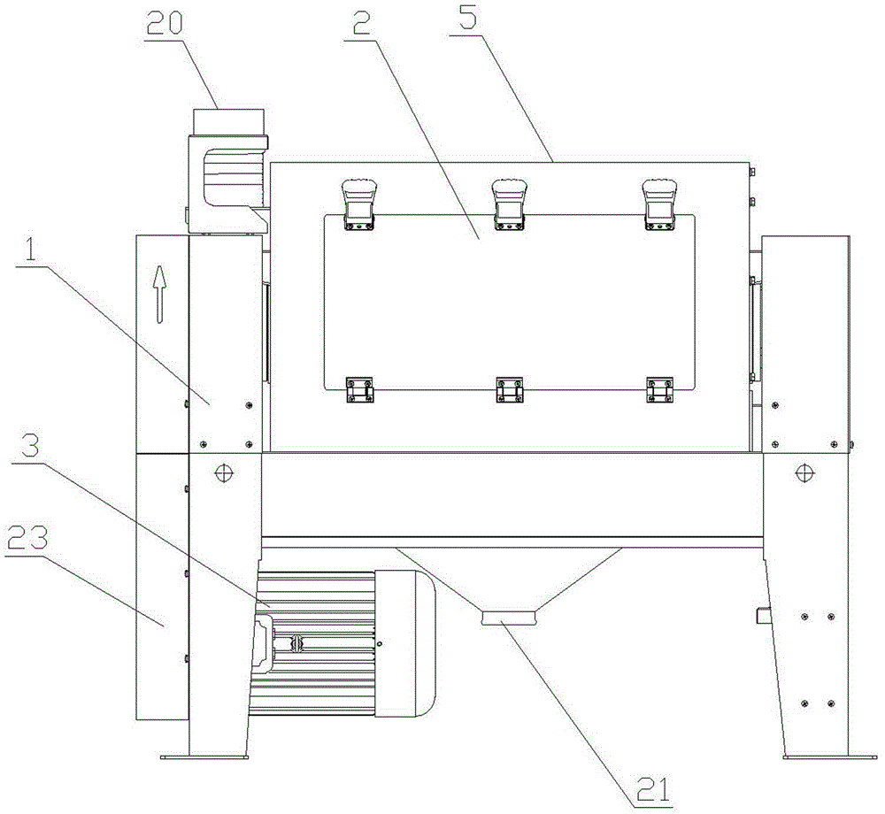
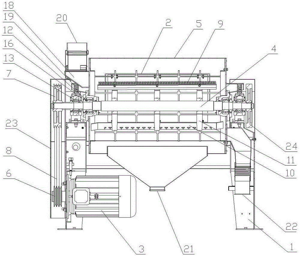
[0035] as attached Figure 1-6As shown, a novel dynamic separation screen includes a frame 1, a screen cylinder 2 arranged on the frame 1 and a motor 3 provided on the frame 1 to provide power for the screen cylinder 2, and the inner wall of the screen cylinder 2 is provided with There is a sieve 15 tensioned by a sieve pressing mechanism 14, and the sieve 15 selects a suitable sieve hole diameter according to the diameter of the material to be screened. Ring, and then the screen 15 is fastened by bolts and screws. The sieve cylinder 2 includes a sieve cylinder main shaft 4 connected to the frame 1 by a sieve cylinder support bearing 13 and a sieve cylinder housing 5 arranged on the sieve cylinder main shaft 4; the sieve cylinder main shaft 4 is an eccentric shaft, and the sieve cylinder main shaft The eccentric distance of 4 is 1.5mm, and the screen cylind...


PUM


Abstract

The invention discloses a novel dynamic separation sieve which comprises a rack, a sieve barrel arranged on the rack and a motor arranged on the rack. A sieve net which is tightened through a sieve net compression mechanism is arranged on the inner wall of the sieve barrel. The sieve barrel comprises a sieve barrel spindle connected to the rack through a supporting bearing and a sieve barrel housing arranged on the sieve barrel spindle. The sieve barrel spindle is an eccentric shaft, the sieve barrel housing is arranged on the sieve barrel spindle through a sieve barrel rotating shaft capable of achieving self-aligning, and a conveyor belt is connected between a driving wheel of the motor and a transmission wheel fixed to one end of the sieve barrel spindle. According to the novel dynamic separation sieve, the eccentric shaft is adopted as the sieve barrel spindle, the sieve barrel makes vibration motion on the rack to prevent materials which are similar to sieve net holes in boundary dimension from being blocked on the sieve net or prevent fine powder from being attached to sieve net wires, the phenomenon of hole blockage is avoided, and a high separation effect is achieved; strong springs are used for fixing the sieve barrel, and the working state that the sieve barrel vibrates instead of rotating is achieved. The equipment does not wholly rotate, so that normal operation of other equipment near the sieve is not affected.

Description

technical field [0001] The invention relates to a screening machine, in particular to a novel dynamic separation screen. Background technique [0002] In the grain processing industry, sieves are important equipment for cleaning, grading, and screening in the entire processing process. The output, efficiency, and life of sieves have a direct impact on subsequent grain processing. In grain processing, crushing and screening are the two main work links. Crushing is to crush grain particles (such as corn, wheat, etc.) to a certain extent through a crusher or a flour mill, and then classify the crushed materials by screening equipment. The crushing equipment continues to crush and reciprocates in this way to realize continuous operation. In this process, the sieving efficiency of grading equipment directly affects the efficiency of flour production. Improving the sieving efficiency of grading equipment is one of the key technologies to improve flour production efficiency. ...

Claims


Application Information

Patent Timeline
Patent Type & Authority Applications(China)
IPC IPC(8): B07B1/28B07B1/46B07B1/48B07B1/42B07B1/50
CPCB07B1/286B07B1/42B07B1/46B07B1/4609B07B1/48B07B1/50
Inventor 李建军吴军永刘素山高鹏刘会杰周锋
Owner HEBEI PINGLE FLOUR MACHINERY GROUP
Why Eureka
Eureka Blog
Learn More