
Position-sensor-free control system and control method for brushless direct current motor

A brushed DC motor and control method technology, applied in the direction of AC motor control, control system, vector control system, etc., can solve the problems of difficulty in determining the position of the motor rotor, inaccurate position signal detection, control failure, etc., to improve the response speed and Control accuracy, simplify calculation process, improve the effect of dynamic response

Inactive Publication Date: 2016-03-09
HARBIN UNIV OF SCI & TECH
View PDF7 Cites 40 Cited by
  • Summary
  • Abstract
  • Description
  • Claims
  • Application Information

AI Technical Summary

Problems solved by technology

However, in the existing line back electromotive force method control FOC algorithm, the EMF method is used for position detection, and the rotor position can only be estimated after a large number of transformation calculations using the rotation component obtained by the detected phase current after Clark transformation, and there is a phase current detection error. Accumulation is applied to rotor position estimation, which leads to inaccurate position signal detection, large voltage vector error, and large motor output torque fluctuation. When the motor is at rest or no-load, the phase current is very small, which will cause the motor rotor position to be determined Difficult to accurately determine rotor position, causing control failure

Method used


Image

  • Position-sensor-free control system and control method for brushless direct current motor
  • Position-sensor-free control system and control method for brushless direct current motor
  • Position-sensor-free control system and control method for brushless direct current motor

Examples


Embodiment Construction

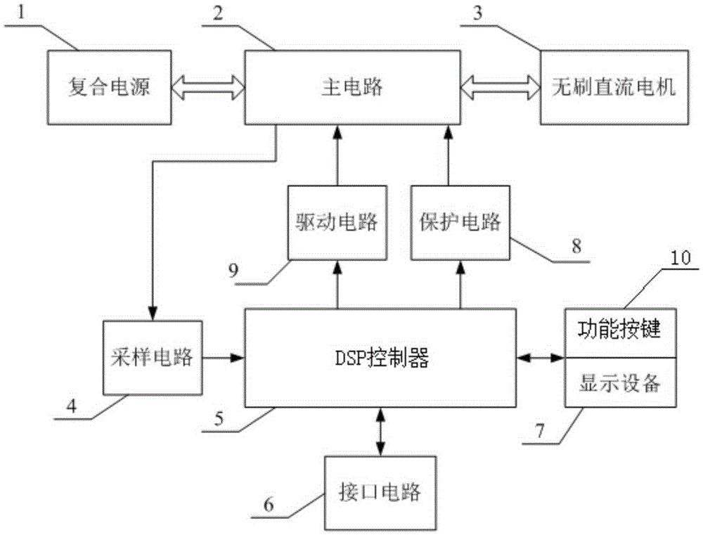
[0021] refer to figure 1 , the brushless DC motor position sensorless control system includes a composite power supply 1 composed of a supercapacitor and a lithium battery, a main circuit 2 composed of a bidirectional DC-DC converter and an inverter, a brushless DC motor 3 and DSP control 5, the composite power supply 1, the main circuit 2 are connected to the brushless DC motor 3 in sequence, the main circuit 2 is connected to the DSP controller 5 through the sampling circuit 4, and the DSP controller 5 is connected to the main circuit through the driving circuit 9 and the protection circuit 8 respectively 2. The DSP controller 5 is connected to the interface circuit 6 , the display device 7 and the function keys 10 .

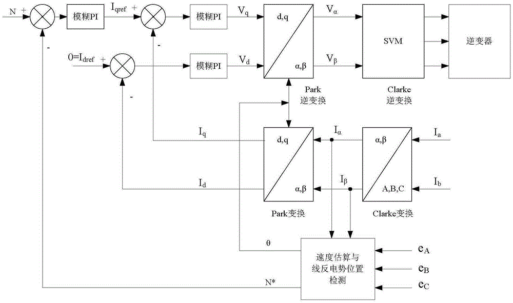
[0022] The DSP controller 5 adopts the digital signal processor TMS320F2812 of TI Company as the main control chip, and the overall working process is: the external control command is sent to the DSP controller 5 by the function button 10 through signal condit...


PUM


Abstract

A position-sensor-free control system and control method for a brushless direct current motor. The system includes a composite power supply, a main circuit, a brushless direct current motor and a DSP controller, the composite power supply, the main circuit and the brushless direct current motor are connected in sequence, the main circuit is connected with the DSP controller through a sampling circuit, the DSP controller is connected with the main circuit through a drive circuit and a protection circuit, and the DSP controller is connected with an interface circuit and s functional key. The method includes the steps of: 1. detecting a phase voltage counter electromotive force signal and a phase current signal; 2. calculating wire counter electromotive force; 3. determining the position of a rotor; 4. performing inverse transformation; and 5. generating a PWM duty ratio. The method provided by the invention detects counter electromotive force of the motor in a starting and low-speed stage through a wire counter electromotive force method, and integrates an improved wire counter electromotive force method in FOC algorithm, thereby simplifying position and speed calculating processes of the FOC algorithm, improving real-time performance and control accuracy of a system, and achieving the purpose of improving dynamic performance of the motor.

Description

Technical field: [0001] The invention relates to the field of control of brushless direct current motors, in particular to a position sensorless control system and control method of brushless direct current motors. Background technique: [0002] In order to obtain accurate rotor position signals, traditional brushless DC motor control systems generally use position sensors such as Hall magneto-sensitive, electromagnetic or photoelectric sensors for detection. However, the use of position sensors not only increases the volume and cost of the motor, but also makes maintenance difficult; at the same time, it cannot adapt to harsh working environments such as high temperature and high humidity, and is not even allowed to be used in some industrial applications; , susceptible to interference from external signals, reducing the reliability of the motor operation. At the same time, the traditional brushless DC motor control method drives the stator in a trapezoidal manner, which w...

Claims


Application Information

Patent Timeline
IPC IPC(8): H02P21/18H02P21/28H02P25/03H02P27/06
CPCH02P21/001H02P25/03H02P27/06
Inventor 周美兰吴磊磊张小明胡玲玲刘占华
Owner HARBIN UNIV OF SCI & TECH
Learn More