Portable millimeter wave passive focal plane imaging system
An imaging system and focal plane technology, applied in the direction of measuring devices, instruments, antenna supports/mounting devices, etc., can solve the problems of large volume and poor portability, and achieve the effects of small volume, light weight, and easy processing
- Summary
- Abstract
- Description
- Claims
- Application Information
AI Technical Summary
Problems solved by technology
Method used
Image


Examples
Embodiment 1
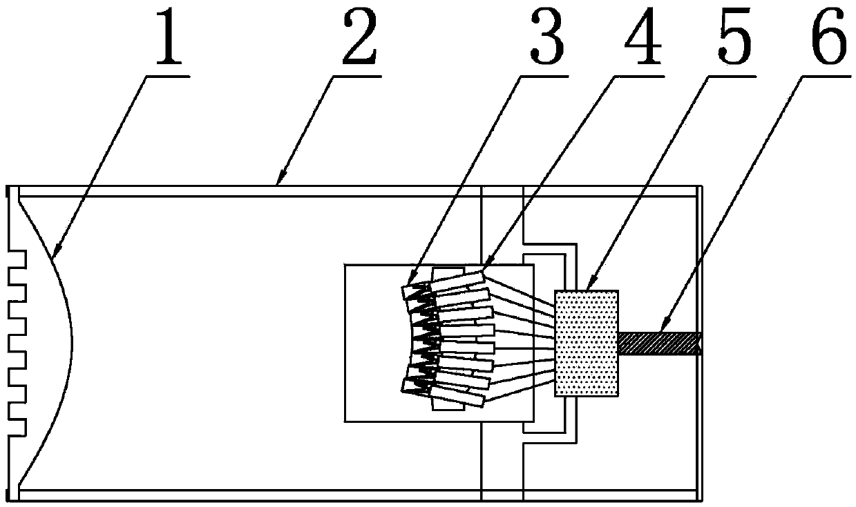
[0036] Such as figure 1 , 2 As shown, a portable millimeter-wave passive focal plane imaging system includes a cylinder 2 with a lens antenna 1 installed at one end, and a focal plane feed array 3 facing the lens antenna 1 is fixed inside the cylinder 2 to pass through the lens antenna 1 The microwave arrives at the focal plane feed source array 3, and the focal plane feed source array 3 is connected to the radiometer receiver group 4, and the radiometer receiver group 4 is connected to the signal conditioning circuit 5, and the signal conditioning circuit 5 is connected to a power supply with signal output and power input ports. The transfer circuit 6, the signal conditioning circuit 5, and the transfer circuit 6 adopt the signal conditioning circuit and the transfer circuit of the traditional millimeter-wave imaging system, the output interface is connected to the electrical signal acquisition card of the computer, and the acquisition card collects the electrical signal outp...
Embodiment 2
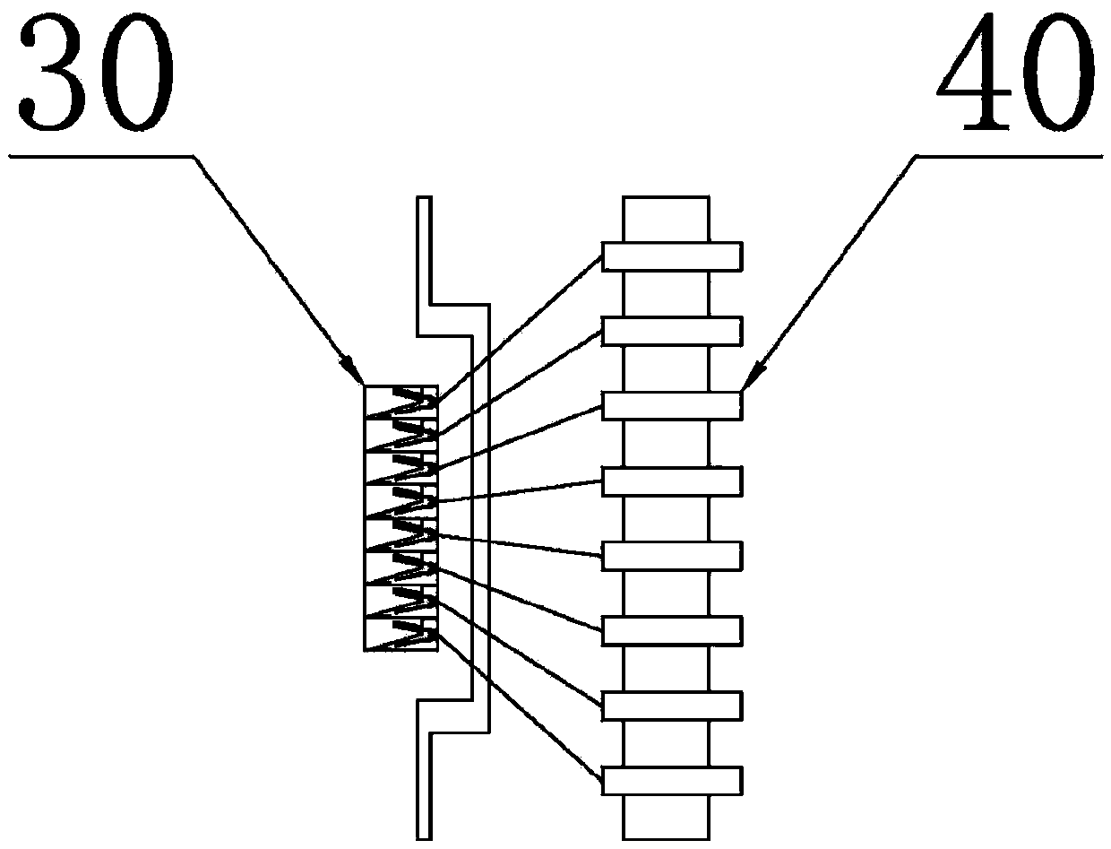
[0050] The portable millimeter-wave passive focal plane imaging system of Embodiment 2 is basically the same as Embodiment 1, the difference being that: image 3 As shown, more than two feed antennas 30 are integrally processed into a focal plane feed array 3, and a plurality of feed antennas are fabricated on a dielectric substrate through photolithography and other processes, and each feed antenna 30 passes through a coaxial Connectors, coaxial cables and coaxial waveguide converters connect radiometer 40 . The focal plane feed array 3 is in the shape of a rectangular sheet, and more than two feed antennas 30 are aligned and arranged in a row. The feed antenna 30 is used as a conjugate linear graded slot antenna and is processed on a whole dielectric substrate, which greatly saves the cost of the imaging system and improves the performance of the portable imaging system.
Embodiment 3
[0052] The portable millimeter-wave passive focal plane imaging system of the third embodiment is basically the same as that of the second embodiment, the difference being that: Figure 4 As shown, the focal plane feed array 3 is fan-shaped, more than two feed antennas 30 are arranged sequentially along an arc, the phase centers of all feed antennas 30 are arranged along the curve, and the arrangement curve equation is the surface equation of the lens.
PUM
 Abstract
Description
Claims
Application Information
 - R&D
- Intellectual Property
- Life Sciences
- Materials
- Tech Scout
- Unparalleled Data Quality
- Higher Quality Content
- 60% Fewer Hallucinations
Browse by: Latest US Patents, China's latest patents, Technical Efficacy Thesaurus, Application Domain, Technology Topic, Popular Technical Reports.
© 2025 PatSnap. All rights reserved.Legal|Privacy policy|Modern Slavery Act Transparency Statement|Sitemap|About US| Contact US: help@patsnap.com