
Magnetorheological fluid braking device

A magneto-rheological fluid and braking device technology, applied in the direction of liquid resistance brakes, brake types, mechanical equipment, etc., can solve the problems of small braking torque and poor heat dissipation, and achieve increased braking torque, fast response speed, The effect of novel device structure

Active Publication Date: 2016-02-24
NORTHEASTERN UNIV
View PDF12 Cites 7 Cited by
  • Summary
  • Abstract
  • Description
  • Claims
  • Application Information

AI Technical Summary

Problems solved by technology

Magneto-rheological brake is one of the applications of magnetorheological fluid. The magnetorheological fluid braking device uses the viscous shear force of magnetorheological fluid to brake. It has the advantages of small size, low energy consumption, and fast response. Rheological fluid brakes have disadvantages such as small braking torque and poor heat dissipation, which restrict its application

Method used


Image

  • Magnetorheological fluid braking device
  • Magnetorheological fluid braking device
  • Magnetorheological fluid braking device

Examples


Embodiment Construction

[0031] The present invention will be described in further detail below in conjunction with embodiment.

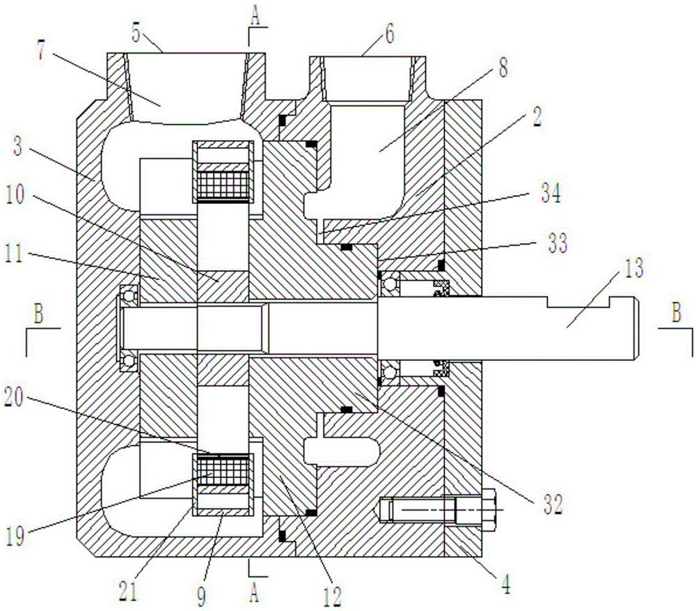
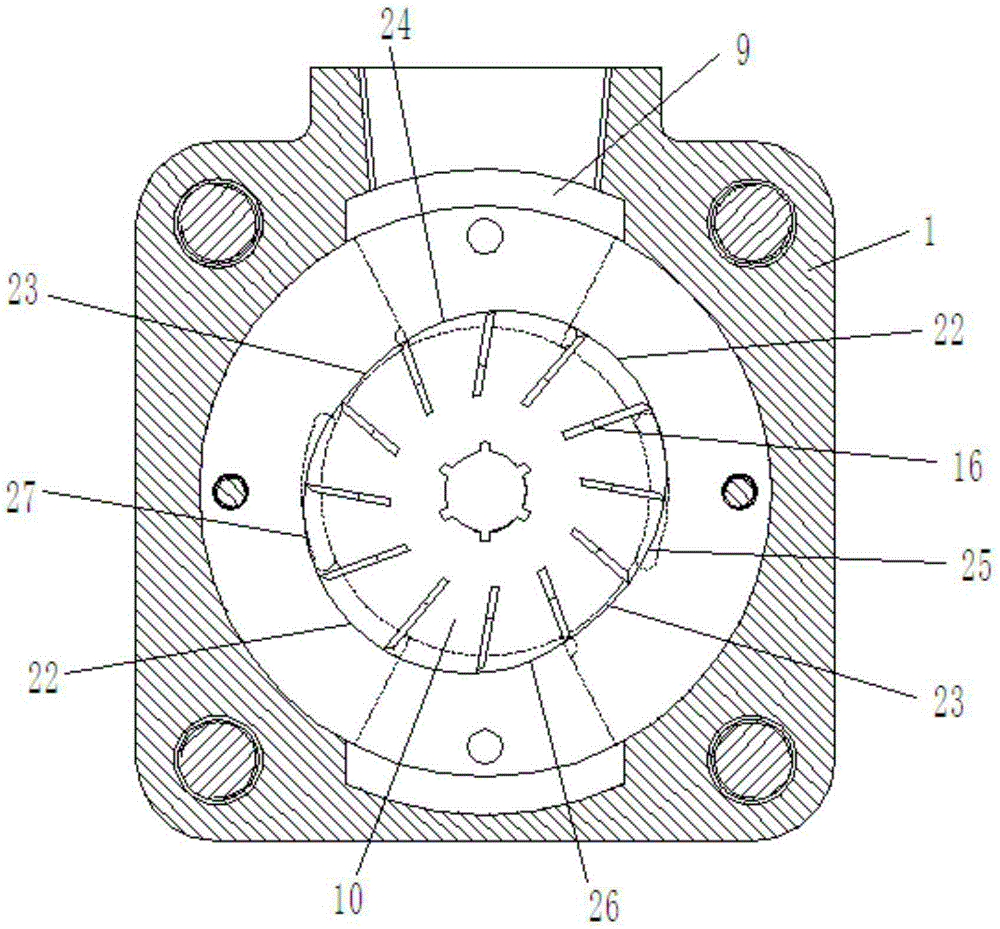
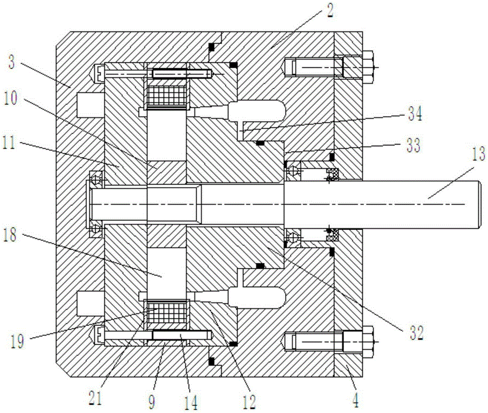
[0032] according to figure 1 and image 3 As shown, a magneto-rheological fluid braking device includes: a housing 1, the housing 1 includes a base 2, the two ends of the base 2 are respectively provided with a left end cover 3 and a right end cover 4, and the housing 1 is provided with an inlet The liquid inlet 5 and the liquid outlet 6, the housing 1 is provided with a liquid inlet channel 7 and a liquid outlet channel 8, the liquid inlet 5 communicates with the liquid inlet channel 7, and the liquid outlet channel 8 communicates with the liquid outlet 6 , the middle part of the housing 1 is a cavity structure, and the stator 9, the rotor 10, the left distribution plate 11, and the right distribution plate 12 are installed in the cavity, the stator 9 is surrounded by the outer side of the rotor 10, and the transmission shaft 13 is connected to the left end cover through ...


PUM


Abstract

The invention discloses a magnetorheological fluid braking device. The magnetorheological fluid braking device comprises a shell. The shell is provided with a liquid inlet and a liquid outlet. A liquid inlet channel and a liquid outlet channel are formed in the shell. The liquid inlet is communicated with the liquid inlet channel, and the liquid outlet channel is communicated with the liquid outlet. A stator, a rotor, a left flow distributing disc and a right flow distributing disc are arranged in an inner cavity in the shell. The stator surrounds the outer side of the rotor. A transmission shaft is inserted in the shell. The rotor, the left flow distributing disc and the right flow distributing disc are arranged on the transmission shaft in a sleeving manner. The transmission shaft drives the rotor to rotate. The rotor is provided with blades. A forming cavity is formed among the stator, the rotor, the left flow distributing disc and the right flow distributing disc and filled with magnetorheological fluid. Magnet exciting coils are arranged at the two ends of the cavity respectively. Magnetism isolation copper sleeves are arranged on the sides, close to the blades, of the magnet exciting coils. Liquid suction holes and liquid pressing holes are formed in the positions, corresponding to the transition curve, on the left flow distributing disc and the right flow distributing disc respectively. The magnetorheological fluid braking device is novel in structure, the braking torque is increased, the defect that an existing magnetorheological fluid braking device is too small in braking torque is overcome, meanwhile, the torque can be continuously adjusted, and the response speed is high.

Description

Technical field: [0001] The invention relates to the technical field of brake devices, in particular to a magneto-rheological fluid brake device. Background technique: [0002] Since Rabinow discovered the rheological properties of magnetorheological fluids in the 1940s, magnetorheological fluids have become an important research direction for smart materials. Magnetorheological fluid is a kind of intelligent fluid material, which is a suspension made of nano-scale soft magnetic particles made of high magnetic permeability and low hysteresis and non-magnetic liquid. When there is no external magnetic field, it exhibits low-viscosity Newtonian fluid characteristics under the action of zero magnetic field, and once an external magnetic field is applied, its fluid properties will change sharply, and it can be changed within a few milliseconds under the action of a magnetic field. The fluid becomes a non-Newtonian fluid, presenting a solid-like state with high viscosity and low...

Claims


Application Information

Patent Timeline
Patent Type & Authority Applications(China)
IPC IPC(8): F16D57/02
Inventor 宋万里王文越金鑫
Owner NORTHEASTERN UNIV
Learn More