


Quick Research
Generate reliable direction feasibility study reports for your R&D in just a few steps.

Technical Q&A
Discover and master advanced knowledge NOW. Basics, ideas, possibilities, all at once.

Find Solutions
As an expert in R&D theories, this can generate solutions to your technical problems instantly.

Evaluate Feasibility
Analyze your overall solution with one click, know your potential R&D risks in advance.

Monitor Landscape
Get weekly tech updates, stay abreast of the latest tech innovations and key insights.
Device and method for depositing modified coating on surface of precision ball
A technology for modifying coating and ball surface, applied in coating, metal material coating process, ion implantation plating, etc., can solve the surface damage of precision ball, cannot guarantee the surface accuracy requirements of ceramic ball, and it is difficult to ensure modification Coating uniformity and other problems, to achieve the effect of improving service life, uniform coating deposition effect, and ensuring dimensional accuracy
- Summary
- Abstract
- Description
- Claims
- Application Information
AI Technical Summary
Problems solved by technology
Method used
Image

Examples
specific Embodiment approach 1
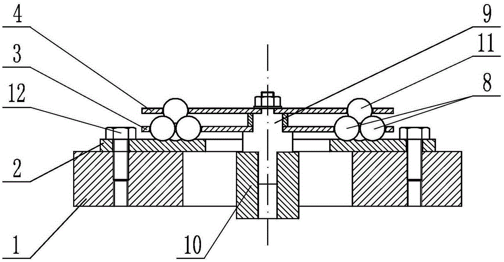
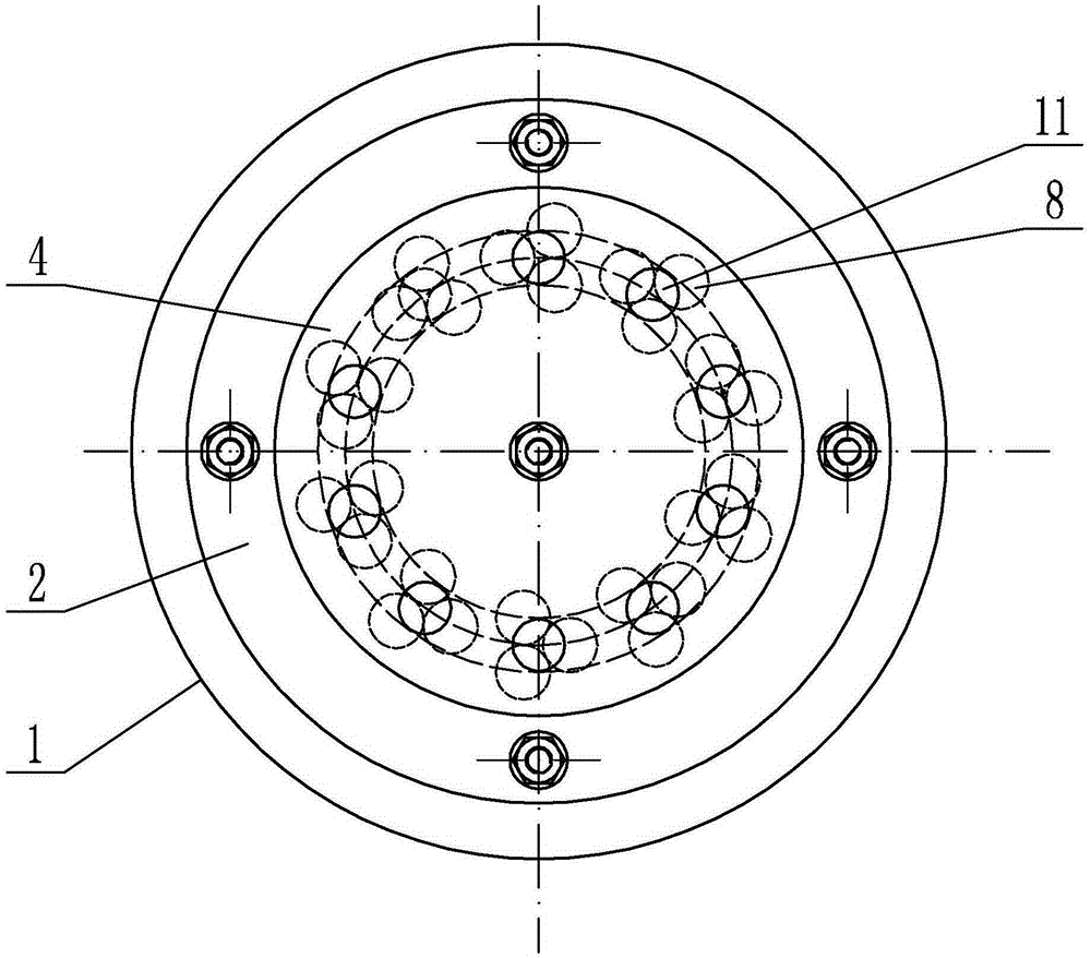
[0026] Specific implementation mode one: combine figure 1 , figure 2 , image 3 , Figure 4 , Figure 5 , Figure 6 and Figure 7 This embodiment is described. This embodiment includes a rotating base 1, a chassis 2, a middle cage 3, an upper cage 4, a fixed shaft 9, a fixed central bushing 10, and a plurality of drive balls 8. The upper cage 4, the middle Both the cage 3 and the chassis 2 are discs, the rotating base 1 is a rotating table of the ion implantation deposition equipment, the chassis 2 is set on the rotating base 1, and the fixed central sleeve 10 is located at the center of the rotating base 1 position, the upper cage 4 and the middle cage 3 are sequentially set on the fixed shaft 9 from top to bottom, and the lower end of the fixed shaft 9 passes through the chassis 2 and is arranged in the fixed central bushing 10, and the bottom of the chassis 2 At least one set of three-phase passages are sequentially processed from inside to outside on the disk surfac...
specific Embodiment approach 2
[0029] Specific implementation mode two: combination figure 2 , Figure 6 and Figure 7 This embodiment is described. In this embodiment, a plurality of positioning holes 6 are evenly arranged along the circumferential direction of the middle cage 3 , and the plurality of precision ball passing holes 7 are evenly arranged along the circumferential direction of the upper cage 4 . In this embodiment, three driving balls 8 form a group and are arranged in one positioning hole 6. The way that a plurality of positioning holes 6 are evenly distributed makes each group of driving balls independent of each other, and a plurality of precision balls pass through the holes 7 evenly. The way of cloth makes mutual influence between a plurality of precision balls 11. Each group of driving balls independently completes the effect of driving the precision ball 11 on it to rotate. Other unmentioned structures and connections are the same as those in the first embodiment.
specific Embodiment approach 3
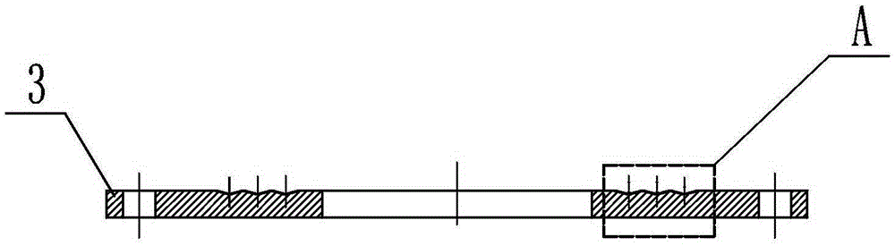
[0030] Specific implementation mode three: combination figure 1 , image 3 , Figure 4 and Figure 5 Describe this embodiment, the groove 5 in this embodiment is a V-shaped groove or an arc-shaped groove. Other unmentioned structures and connections are the same as those in the first or second embodiment.
[0031] Specific implementation mode four: combination figure 1This embodiment will be described. In this embodiment, the fixed shaft 9 and the fixed central sleeve 10 are screwed together. Such a setting shows a stable connection effect in the sample test. Other unmentioned structures and connections are the same as those in the third embodiment.
[0032] Specific implementation mode five: combination figure 1 and figure 2 This embodiment will be described. In this embodiment, the upper cage 4 and the middle cage 3 are fixedly connected to the fixed shaft 9 sequentially from top to bottom. Such setting effectively fixes the positions of the upper cage 4 and the mi...
PUM
| Property | Measurement | Unit |
|---|---|---|
| Diameter | aaaaa | aaaaa |
| Thickness | aaaaa | aaaaa |
| Diameter | aaaaa | aaaaa |
Abstract
Description
Claims
Application Information
 - R&D Engineer
- R&D Manager
- IP Professional
- Industry Leading Data Capabilities
- Powerful AI technology
- Patent DNA Extraction
Browse by: Latest US Patents, China's latest patents, Technical Efficacy Thesaurus, Application Domain, Technology Topic, Popular Technical Reports.
© 2024 PatSnap. All rights reserved.Legal|Privacy policy|Modern Slavery Act Transparency Statement|Sitemap|About US| Contact US: help@patsnap.com