Connecting rod non-flash die forging closed die and forging process for the manufacture of key parts of automobile engines

A flash-free, die-forging technology, applied to engine components, manufacturing tools, mechanical equipment, etc., can solve the problems of forging scrap, forging flash, large residual stress, etc., achieve stable operation without impact, ensure stability, reduce cost effect

Active Publication Date: 2017-08-15
江苏南洋中京科技有限公司
View PDF10 Cites 0 Cited by
  • Summary
  • Abstract
  • Description
  • Claims
  • Application Information

AI Technical Summary

Problems solved by technology

However, the mold structure is vertical parting, and there is not enough clamping force. When forging forgings such as connecting rods, to accurately form the I-shaped section requires a clamping force greater than the forming force. Flashes, sharp corners and parts that are difficult to fill will cause the forging to be scrapped due to insufficient filling; the device has only one die forming punch, resulting in uneven metal flow in the forging body and large residual stress

Method used


Image

  • Connecting rod non-flash die forging closed die and forging process for the manufacture of key parts of automobile engines
  • Connecting rod non-flash die forging closed die and forging process for the manufacture of key parts of automobile engines
  • Connecting rod non-flash die forging closed die and forging process for the manufacture of key parts of automobile engines

Examples


Embodiment Construction

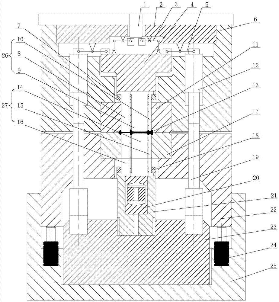
[0031] Such as figure 1 As shown, the present embodiment comprises: upper punch 26, lower punch 27, upper die 11 arranged on upper die holder 6 and lower die 17 arranged on lower die holder 22, wherein: upper punch 26 and The lower punch 27 is movably arranged in the middle part of the upper die 11 and the middle part of the lower die 17 respectively. The upper punch 26, the lower punch 27, the upper die 11 and the lower die 17 form a closed die chamber.

[0032] The lower mold base 22 is arranged in the mold frame 25 , and the two ends of the lower mold base 22 are connected to the bottom of the mold frame 25 through nitrogen springs 24 . A pivot support seat 23 is arranged in the groove in the middle of the mold frame 25 and is located between the nitrogen springs 24 at both ends. The lower mold base 22 is connected with the upper mold base 6 through the pivot 19, and the pivot 19 is arranged on both sides of the pivot support base 23, so that the lower mold base 22 and th...


PUM

PropertyMeasurementUnit
particle sizeaaaaaaaaaa

Abstract

The invention discloses a link flashless closed-die forging die for automobile engine key part manufacturing and a forging process. The die comprises an upper male die, a lower male die, a link mechanism, an upper female die arranged on an upper die holder and a lower female die arranged on a lower die holder, wherein a connection end of the lower male die is connected with a lower plunger chip support seat, and a working end of the lower male die is arranged at the middle part of the lower female die in a penetrating manner; a connection end of the upper male die is connected with a lower end of an upper plunger chip cushion block, and a working end of the upper male die is arranged at the middle part of the upper female die in a penetrating manner; the link mechanism is arranged at an upper end of the upper plunger chip cushion block; and when forged pieces are forged, the upper male die, the upper female die, the lower male die and the lower female die form a closed die impression. The device ensures the stability of the geometric dimensions of the forged pieces, controls a mass deviation to be not greater than 30g, reduces the material consumption, and decreases the cost; after each link is subjected to the subsequent machining of quenching, annealing and the like, the strength thereof is double of that of a common link, and the sectional inertia moment thereof is stably changed. The die is stable in running and impact-free during the whole forging process.

Description

technical field [0001] The invention relates to a technology in the field of manufacturing key parts of an automobile engine, in particular to a flash-free forging block die for connecting rods and a forging process for manufacturing key parts of an automobile engine. Background technique [0002] With the improvement of ecological environmental protection standards, it is required to improve the strength, precision and balance of parts without increasing the mass and size of automotive engine connecting rods. The connecting rods of automobile engines generally adopt open die forging, and there are flash grooves around the open die bore. During the forging process, excess metal can flow into the flash grooves. After the forging is completed, the connecting rod must be trimmed and shaped, which not only increases the material consumption, but also exposes the metal streamline on the parting surface of the trimmed connecting rod, forming a source of stress corrosion. Due to t...

Claims


Application Information

Patent Timeline
Patent Type & Authority Patents(China)
IPC IPC(8): B21J13/02B21J5/02B21K3/00
CPCB21J5/025B21J13/02B21K3/00
Inventor 汪磊徐杰王以华
Owner 江苏南洋中京科技有限公司
Why Eureka
Try Eureka