
Finfet thermal protection methods and related structures

A substrate and drain region technology, which is applied in electrical components, semiconductor/solid-state device manufacturing, circuits, etc., can solve problems such as weakening device performance, adverse effects of high-mobility materials, and degradation of high-mobility materials

Active Publication Date: 2016-02-10
TAIWAN SEMICON MFG CO LTD
View PDF6 Cites 2 Cited by
  • Summary
  • Abstract
  • Description
  • Claims
  • Application Information

AI Technical Summary

Problems solved by technology

However, existing semiconductor process flows require high temperature processing during various steps of the overall process flow, such as oxide anneal, silicon nitride deposition, or dopant diffusion and activation anneal, which imposes Negative Effects
In particular, high-mobility materials are unlikely to remain thermally stable under high-temperature conditions encountered during typical semiconductor processing, leading to degradation of high-mobility materials and weakened device performance
Therefore, the existing technology can not fully meet the requirements of all aspects

Method used


Image

  • Finfet thermal protection methods and related structures
  • Finfet thermal protection methods and related structures
  • Finfet thermal protection methods and related structures

Examples


Embodiment Construction

[0030] The following disclosure provides many different embodiments or examples for implementing different features of the presented subject matter. Specific examples of components and arrangements are described below to simplify the present disclosure. Of course, these are examples only and are not intended to limit the invention. For example, in the following description, forming a first component over or on a second component may include an embodiment in which the first component and the second component are formed in direct contact, and may also include an embodiment in which the first component and the second component are formed in direct contact. An embodiment in which an additional component may be formed between such that the first component and the second component may not be in direct contact. In addition, the present invention may repeat reference numerals and / or letters in various instances. This repetition is for simplicity and clarity, and does not in itself i...


PUM


Abstract

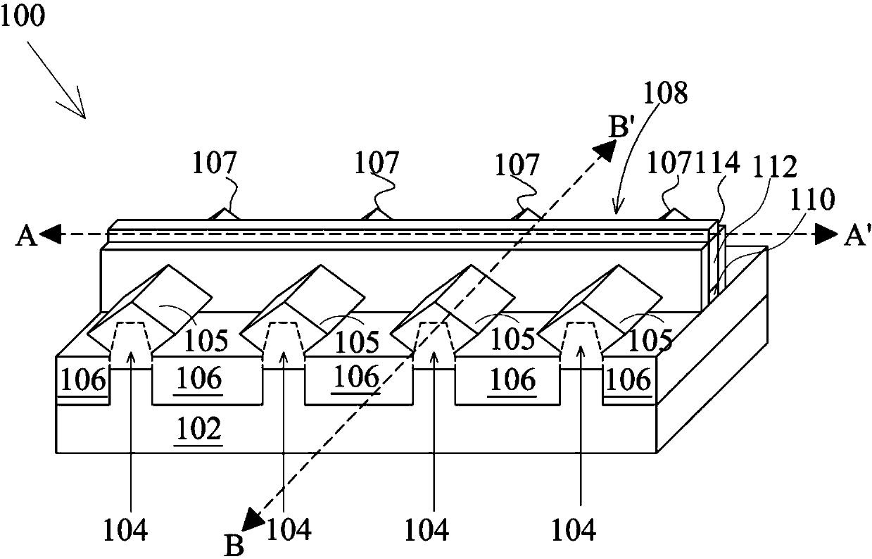
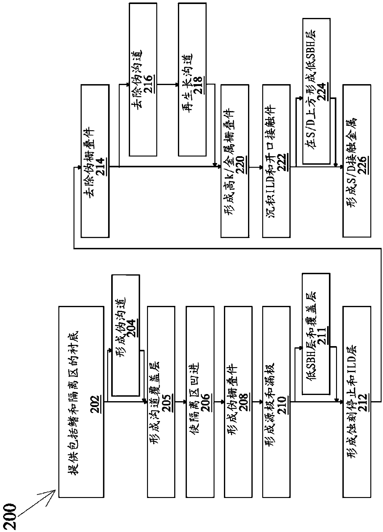
A method and structure for protecting high-mobility materials from exposure to high temperature processes includes providing a substrate having at least one fin extending therefrom. The at least one fin includes a dummy channel and source / drain regions. A dummy gate stack is formed over the dummy channel. A first inter-layer dielectric (ILD) layer is formed on the substrate including the fin. The first ILD layer is planarized to expose the dummy gate stack. After planarizing the first ILD layer, the dummy gate stack and the dummy channel are removed to form a recess, and a high-mobility material channel region is formed in the recess. After forming the high-mobility material channel region, contact openings are formed within a second ILD layer overlying the source / drain regions, and a low Schottky barrier height (SBH) material is formed over the source / drain regions.

Description

technical field [0001] The present invention generally relates to the field of semiconductors, and more particularly, to a method of manufacturing a FINFET. Background technique [0002] The electronics industry has seen an increasing demand for smaller and faster electronic devices capable of simultaneously supporting a greater number of increasingly complex and sophisticated functions. Accordingly, there is a continuing trend in the semiconductor industry to manufacture low cost, high performance and low power integrated circuits (ICs). Today, these goals have been largely achieved by scaling down semiconductor IC dimensions (eg, minimum feature size), thereby increasing production efficiency and reducing associated costs. However, this scaling also increases the complexity of the semiconductor manufacturing process. Therefore, the continuous progress of semiconductor ICs and devices also requires the progress of semiconductor manufacturing processes and technologies. ...

Claims


Application Information

Patent Timeline
IPC IPC(8): H01L21/331H01L29/78
CPCH01L29/66545H01L29/785H01L29/1054H01L29/66795H01L21/324H01L21/31053
Inventor 黄玉莲
Owner TAIWAN SEMICON MFG CO LTD
Learn More