Plate type heat pipe and novel pipeline

A plate type, heating tube technology, applied in the mechanical field, can solve the problems of easy leakage, bad products, waste, etc., and achieve the effects of good toughness, mass production, and simple production

Active Publication Date: 2016-02-03
中鼎创元(北京)新能源有限公司
View PDF6 Cites 2 Cited by
  • Summary
  • Abstract
  • Description
  • Claims
  • Application Information

AI Technical Summary

Problems solved by technology

[0002] Nowadays, heat pipes are gradually recognized by all walks of life because of their high heat transfer efficiency, small space requirements, and wide application range. The application of copper heat pipes can be regarded as a relatively mature field, but it is limited by its copper material and mandrel processing. Due to the limitations of the process, it is still impossible to make the diameter and length bigger and longer. What's more, the copper tubes are all made of round tubes. In practical applications, in order to have more contact with the heating plane, more After processing, it is flattened and bent into shape. The heat transfer efficiency of the flattened round copper tube will be reduced, and the copper material is easy to form tiny cracks during the extrusion process. It brings hidden dangers, such as notebook radiators will have poor heat dissipation after being used for a period of time, the heat pipe will fail, and the heat pipe needs to be replaced, which will bring trouble to people's normal life; another example is because of the length of the copper heat pipe. There are limitations, and it can't meet the heat conduction needs of medium and long distances. In addition, because the copper heat pipe has only one heat transfer channel, the heat is converted and conducted in its closed interior, but if any part of the entire heat pipe is not sealed, it will appear. If cracks or air leaks occur, the entire heat pipe will be extremely ineffective, resulting in a large number of defective products and waste
The original pipeline still has the disadvantages of difficult heat control and easy leakage

Method used


Image

  • Plate type heat pipe and novel pipeline
  • Plate type heat pipe and novel pipeline
  • Plate type heat pipe and novel pipeline

Examples


Embodiment 2

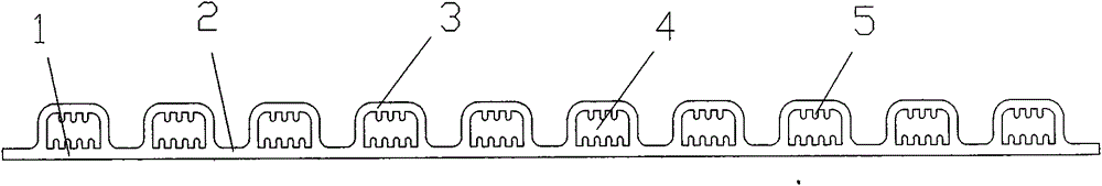
[0039] combine Figure 5 , embodiment two;

[0040] A plate heating tube, characterized in that it includes a pipe wall, the outer wall of the pipe wall contains more than one heat transfer channel 1, the inner wall of the heat transfer channel 1 contains capillary grooves 5, and the inside of the heat transfer channel 1 There is a heat transfer medium, and the capillary grooves 5 are raised strips. The substantive technical effect of the technical solution here is that when the pipeline here is used as a thermal insulation device, the original thermal insulation method of the thermal insulation cotton is changed in one fell swoop, but more than one external heat transfer channel 1 internal The heating liquid can be passed through, so that the pipeline becomes a real heating pipeline, rather than a simple passive insulation, and can be processed while being transported.

[0041] The outside can also be wrapped with a layer of insulation board.

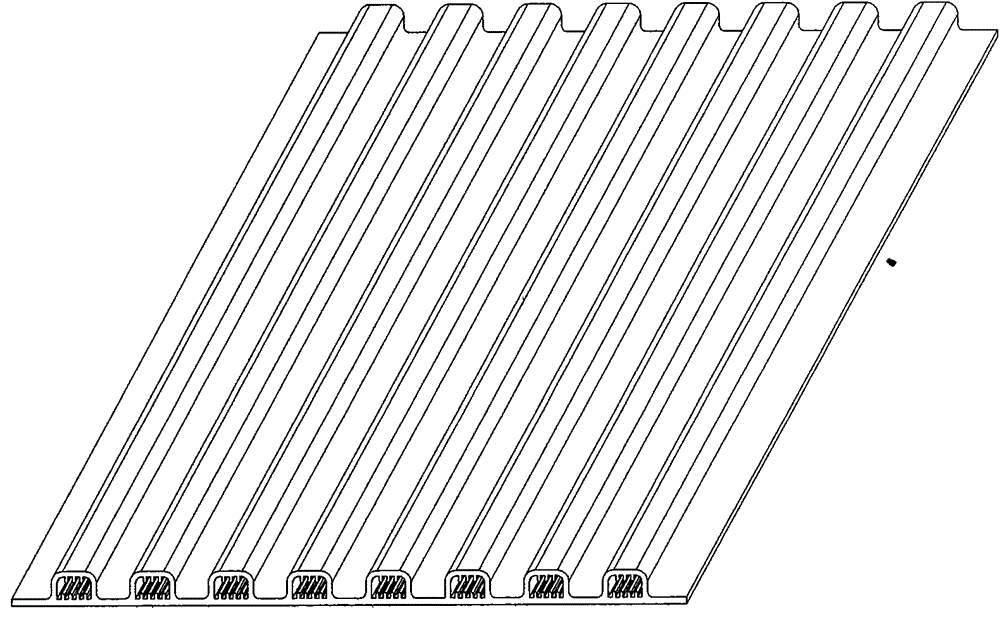
[0042] combine Image 6 , e...


PUM


Abstract

The invention relates to the field of machinery, in particular to a plate type heat pipe and a novel pipeline. The plate type heat pipe comprises a body which comprises a bottom wall. The upper side of the bottom wall is provided with one or more heat transfer channels. The inner walls of the heat transfer channels are provided with capillary grooves. Heat transfer media are arranged in the heat transfer channels. The capillary grooves are convex strip-shaped objects. The plate type heat pipe and the novel pipeline have the beneficial effects of being easy to manufacture, beneficial to batch production and extremely high in flexibility. The body is provided with heat conductors, and connectors are arranged between the heat conductors. The connectors are made of aluminum which is a good heat conducting material and has good toughness. In order to meet the requirement that the heat conductors make contact with various heat sources, the heat conductors different in width can be obtained freely in a cutting manner and other manners. The difficulty that as for copper pipes and common flat plate heat pipes, heat dissipation of the outer circles and the inner circles of circular or semicircular heat conductors cannot be achieved is overcome. The plate type heat pipe and the novel pipeline are worthy of being popularized on a large scale.

Description

technical field [0001] The invention relates to the mechanical field, in particular to a plate heat pipe and a new pipe. Background technique [0002] Nowadays, heat pipes are gradually recognized by all walks of life because of their high heat transfer efficiency, small space requirements, and wide application range. The application of copper heat pipes can be regarded as a relatively mature field, but it is limited by its copper material and mandrel processing. Due to the limitations of the process, it is still impossible to make the diameter and length bigger and longer. What's more, the copper tubes are all made of round tubes. In practical applications, in order to have more contact with the heating plane, more After processing, it is flattened and bent into shape. The heat transfer efficiency of the flattened round copper tube will be reduced, and the copper material is easy to form tiny cracks during the extrusion process. It brings hidden dangers, such as notebook r...

Claims


Application Information

Patent Timeline
Patent Type & Authority Applications(China)
IPC IPC(8): F28D15/04
Inventor 张运利陆柯
Owner 中鼎创元(北京)新能源有限公司
Why Eureka
Try Eureka