Soot blowing device used for circular flue of coal-fired power plant
A technology of soot blowing device and coal-fired power plant, which is applied in the direction of combustion method, treatment of combustion products, removal of solid residue, etc., can solve problems such as easy ash accumulation in circular flue, and solve the problem of ash accumulation in the flue, The effect of soot blowing is obvious and the structure is simple
- Summary
- Abstract
- Description
- Claims
- Application Information
AI Technical Summary
Problems solved by technology
Method used
Image

Examples
Embodiment 1
[0019] A soot blowing device for a circular flue of a coal-fired power plant, comprising a plurality of nozzles arranged on an inclined surface inside the circular flue, the angle between the spray direction of the nozzle output end and the inclined surface is 0-5°, The height of the nozzle is 0.02~0.1 times the diameter of the circular flue, the diameter of the nozzle is greater than or equal to 0.01 times the diameter of the circular flue, and the distance between adjacent nozzles is less than or equal to 0.9 times the diameter of the circular flue.
Embodiment 2
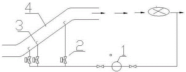
[0021] This embodiment is improved on the basis of Embodiment 1. The soot blowing device for the circular flue of a coal-fired power plant also includes a regulating valve and a booster pump. One end of the regulating valve is connected to the input end of the nozzle. The other end of the regulating valve is connected with the booster pump.
[0022] The air volume drawn by the induced draft fan passes through the booster pump, passes through the regulating valve and then enters the nozzle. A regulating valve controls the speed at which the nozzle blows out. The frequency of use is once a day below 50% of the equivalent continuous operation rating, and the blowing sequence is from upstream to downstream. In order to keep the nozzle clean, a small amount of air volume should be maintained. At the same time, it should run continuously before the nozzle is shut down.
[0023] Parameters such as nozzle shape, installation height, installation angle and spray speed depend on the ...
Embodiment 3
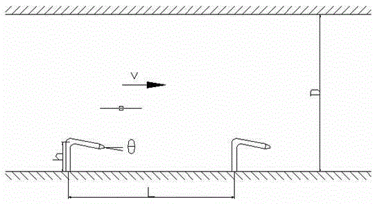
[0026] The verification test is carried out on the inclined flue model, and the main parameters of the model are as follows:
[0027] Flue diameter Nozzle diameter nozzle height nozzle angle blowing speed Nozzle spacing Soot accumulation height D=800mm d=10mm h=50mm 5° 50m / s L=70mm H=15mm
[0028] The test verifies that the accumulated ash within 800mm can be completely removed within 3 minutes. Add the amount of accumulation accumulated over time to convert the actual flue, and the accumulated soot can be removed in about 40 minutes. The test demonstrates that the soot blowing system is easy to install and the soot blowing effect is obvious.
PUM
 Abstract
Description
Claims
Application Information
 - R&D
- Intellectual Property
- Life Sciences
- Materials
- Tech Scout
- Unparalleled Data Quality
- Higher Quality Content
- 60% Fewer Hallucinations
Browse by: Latest US Patents, China's latest patents, Technical Efficacy Thesaurus, Application Domain, Technology Topic, Popular Technical Reports.
© 2025 PatSnap. All rights reserved.Legal|Privacy policy|Modern Slavery Act Transparency Statement|Sitemap|About US| Contact US: help@patsnap.com