Resource unit mapping method and device
A technology of resource unit and mapping method, applied in the field of communication, can solve the problem of long time-consuming mapping process, achieve the effect of scattered and concentrated errors, improve efficiency, and shorten mapping time
- Summary
- Abstract
- Description
- Claims
- Application Information
AI Technical Summary
Problems solved by technology
Method used
Image
Examples
Embodiment 1
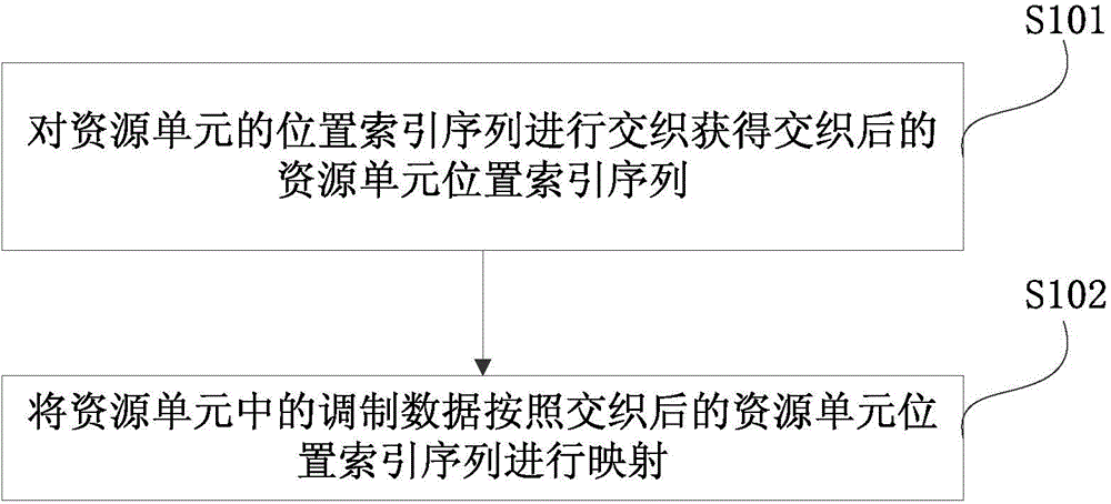
[0050] This embodiment provides a resource unit mapping method, please refer to figure 1 , including the following steps:
[0051] Step S101: Interleave the position index sequence of the resource unit to obtain the interleaved resource unit position index sequence;
[0052] Step S102: Map the modulated data in the resource unit according to the interleaved resource unit position index sequence.
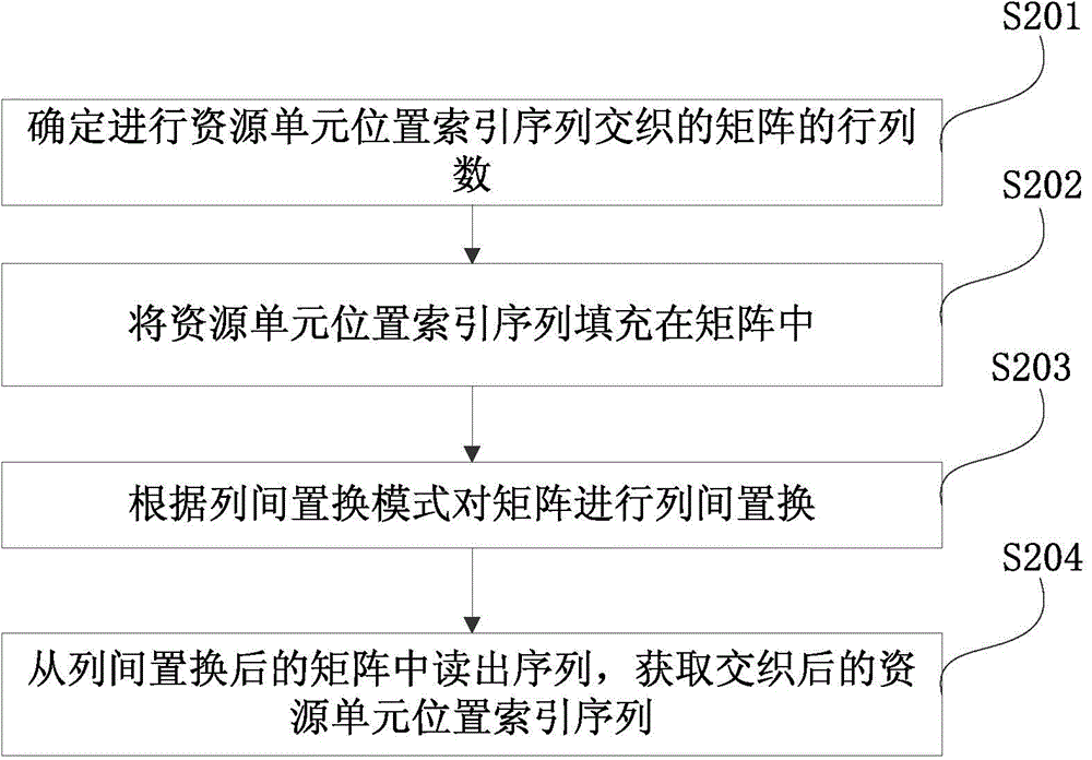
[0053] In this embodiment, the interleaving process on the resource unit position index sequence only needs to be performed once during power-on initialization, and does not need to be performed once during each mapping. Among them, there are many ways to interleave the resource unit position index sequence, and this embodiment provides a common way, please refer to figure 2 , the method specifically includes the following steps:
[0054] Step S201: Determine the number of rows and columns of the matrix for interleaving the resource unit position index sequence;
[...
Embodiment 2
[0065] This embodiment takes PDCCH resource unit mapping as an example to illustrate the resource unit mapping method provided by the present invention, where the resource unit position index sequence is: r(0),...,r(M-1).
[0066] Firstly, the resource unit position index sequence is interleaved, and the interleaving process is as follows:
[0067] a) Let C=32 be the number of columns of the matrix, and the sequence numbers of each column of the matrix are 0, 1, 2, ..., C-1 from left to right.
[0068] b) The row number R of the matrix is the smallest integer satisfying the following formula:
[0069] M≤(R×C)
[0070] The serial numbers of each row of the matrix are 0, 1, 2, ..., R-1 from top to bottom. M is the total number of data in the resource unit location index sequence.
[0071] c) If (R×C)>M, add N=(R×C-M) virtual position indexes at the head, so that x k = ,k=0,1,...,N-1. Then, x N+k =r(k)(k=0,1,...,M-1), starting from row 0 and column 0 of t...
Embodiment 3
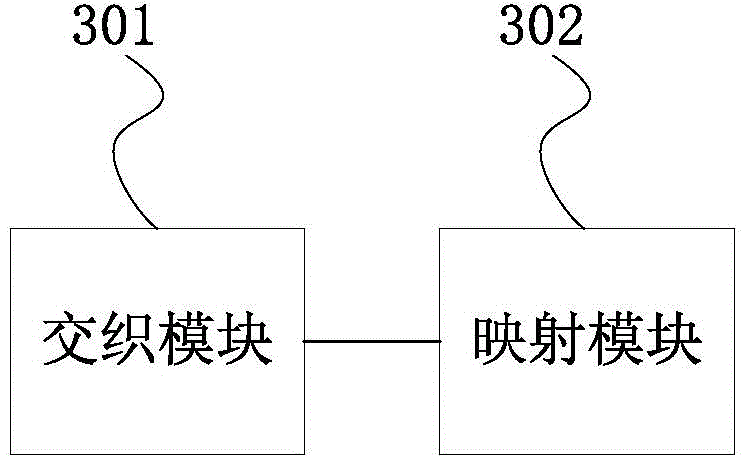
[0081] This embodiment provides a resource unit mapping device, please refer to image 3 , the device mainly includes: an interleaving module 301 and a mapping module 302; the interleaving module 301 is used to interleave the position index sequence of the resource unit to obtain the interleaved resource unit position index sequence; the mapping module 302 is used to convert the modulated data in the resource unit Mapping is performed according to the interleaved resource unit position index sequence.
[0082] In this example, see Figure 4 The interleaving module 301 also includes a row and column number determination submodule 3011, a data filling submodule 3012, an inter-column replacement submodule 3013 and a sequence reading submodule 3014; the row and column number determination submodule 3011 is used to determine the resource unit position index sequence interleaving The number of rows and columns of the matrix; the data filling sub-module 3012 is used to fill th...
PUM
 Abstract
Description
Claims
Application Information
 - R&D
- Intellectual Property
- Life Sciences
- Materials
- Tech Scout
- Unparalleled Data Quality
- Higher Quality Content
- 60% Fewer Hallucinations
Browse by: Latest US Patents, China's latest patents, Technical Efficacy Thesaurus, Application Domain, Technology Topic, Popular Technical Reports.
© 2025 PatSnap. All rights reserved.Legal|Privacy policy|Modern Slavery Act Transparency Statement|Sitemap|About US| Contact US: help@patsnap.com


