
Planetary gear triangular rotor engine

A triangular rotor, planetary gear technology, applied in combustion engines, machines/engines, internal combustion piston engines, etc., can solve the problems of small compression ratio, insufficient power, large volume, etc., to reduce energy loss, low fuel consumption, and volume. small effect

Active Publication Date: 2017-11-03
ANHUI QUANCHAI TIANHE MACHINERY
View PDF6 Cites 0 Cited by
  • Summary
  • Abstract
  • Description
  • Claims
  • Application Information

AI Technical Summary

Problems solved by technology

[0003] The present invention provides a planetary gear type triangular rotor engine, which overcomes the shortcomings of the above-mentioned prior art, and can effectively solve the problem of the relatively large volume of the existing triangular piston rotary engine. Large, small compression ratio, insufficient power, its structure is reasonable and compact, the compression ratio is large, it also reduces the difficulty of processing and assembling the engine main shaft, facilitates repair and maintenance, and improves the power performance of the engine

Method used

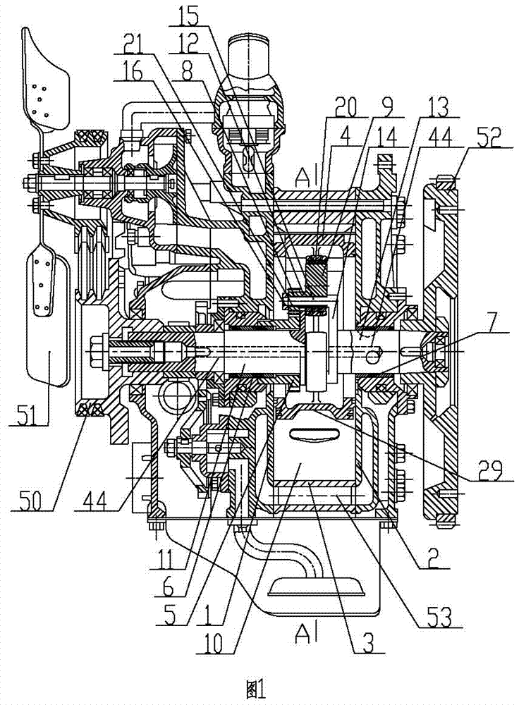

Image

  • Planetary gear triangular rotor engine
  • Planetary gear triangular rotor engine
  • Planetary gear triangular rotor engine

Examples


Embodiment 1

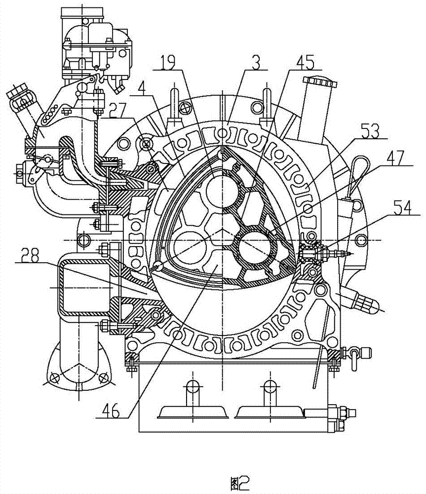
[0037] Embodiment one: as attached figure 2 Shown, the right part of cylinder block 3 is equipped with spark plug 54, and the flashover end of spark plug 54 is facing the inside of cylinder cavity and can flashover ignites the mixed gas in the combustion chamber pit 29, and the terminal of spark plug 54 is connected with the outside world by wire. The positive poles of the power supply are electrically connected together, and the cylinder block 3 is electrically connected together with the negative poles of the external power supply through wires. When the present invention is a gasoline engine, it is necessary to ignite the mixed gas in the pit 29 of the combustion chamber through the timing flashover of the spark plug 54 .

Embodiment 2

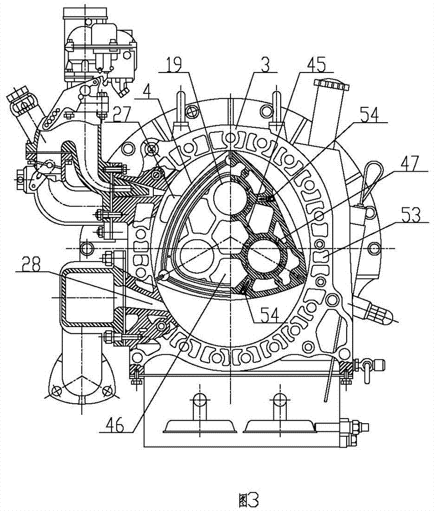
[0038] Embodiment two: as attached image 3 As shown, spark plugs 54 are respectively installed on each arc surface of the triangular rotor 4, and the flashover end of the spark plug 54 is located in the combustion chamber pit 29 and can flash over and ignite the mixed gas in the combustion chamber pit 29, and the terminal of the spark plug 54 The positive pole of the external power supply is electrically connected through wires, carbon brushes and ignition coils, and the cylinder block 3 is electrically connected with the negative pole of the external power supply through wires. By installing the spark plug 54 on each arc surface of the triangular rotor 4, when each arc surface rotates to the right part of the cylinder block 3 in turn, the terminal of the spark plug 54 is connected to the high voltage circuit instantaneously through the carbon brush and the cylinder block 3 to cause flashover , ignite the mixed gas in the corresponding combustion chamber pit 29 at this time, ...


PUM


Abstract

The invention relates to the technical field of internal combustion engines, in particular to a planet gear type triangular rotor engine. The planet gear type triangular rotor engine comprises a front end cover, a rear end cover, an air cylinder body, a triangular rotor, a center gear, a three-fork main shaft assembly and a planet connecting wheel. The front end cover is fixedly installed at the front end of the air cylinder body. The rear end cover body is fixedly installed at the rear end of the air cylinder body. The planet gear type triangular rotor engine is reasonable and compact in structure and convenient to use. Combustible gas expands and acts to drive the triangular rotor to rotate, the triangular rotor drives the three-form main shaft assembly to rotate through the planet connecting wheel, and power is output. Compared with an eccentric main shaft of an existing known triangular rotor engine, the gas compression ratio of an air cylinder is increased, the size of the engine is reduced, the stress condition of an original eccentric triangular rotor is improved, the energy consumption is reduced, and finally the dynamic performance of the engine is improved. Compared with a reciprocated piston type internal combustion engine with the same volume, the planet gear type triangular rotor engine has the beneficial effects of being large in power, low in oil consumption, small in size and wide in rotating speed range.

Description

technical field [0001] The invention relates to the technical field of internal combustion engines, and relates to a planetary gear type triangular rotor engine. Background technique [0002] At present, the internal combustion engines used in automobiles are generally reciprocating piston four-stroke internal combustion engines, which push the piston to reciprocate in the cylinder through gas expansion to perform work, and convert the reciprocating motion into the rotary motion of the main shaft through the connecting rod crank to work. Because the intake valve port and exhaust valve port and the intake and exhaust passages are relatively narrow, the intake and exhaust are not smooth, and a part of energy is always consumed in the process of converting reciprocating motion into rotary motion, which results in the present situation. The efficiency of the double-piston four-stroke internal combustion engine is low, and the crank reciprocating parts make the mechanism of the e...

Claims


Application Information

Patent Timeline
Patent Type & Authority Patents(China)
IPC IPC(8): F02B53/00F02B55/08F02B55/02F02B53/14
CPCY02T10/12
Inventor 李平原
Owner ANHUI QUANCHAI TIANHE MACHINERY
Learn More