
Brake-by-wire and pedal-force feedback system and braking method

A technology of brake-by-wire and feedback system, which is applied in the direction of brake transmission, brake, transportation and packaging, etc. It can solve problems such as bad feeling, pedal vibration, pressure coupling, etc., avoid processing difficulty and leakage problems, and realize independent The effect of control

Active Publication Date: 2016-01-27
ZHEJIANG WANXIANG PRECISION IND +1
View PDF6 Cites 5 Cited by
  • Summary
  • Abstract
  • Description
  • Claims
  • Application Information

AI Technical Summary

Problems solved by technology

[0002] Existing brake-by-wire systems, such as electronic hydraulic control systems, use an electronic brake pedal, but the brake pressure is provided by a plunger pump driven by a motor, and a high-pressure accumulator is used to store pressure, and the backup brake system More isolation solenoid valves are used in the system, and the whole system has more components and higher cost
In addition, in the existing braking system, the brake master cylinder is usually divided into a working chamber and a liquid replenishing chamber, which has a complex structure, a long braking path, and a slow brake pressure response.
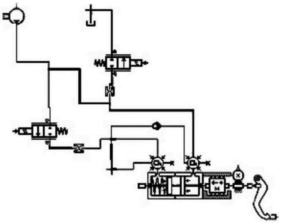
like figure 1 As shown, the existing brake-by-wire and pedal force feedback systems, the pedal force control system and the system pressure control system have pressure coupling problems. When ABS brakes, the pedals vibrate and feel bad.

Method used


Image

  • Brake-by-wire and pedal-force feedback system and braking method
  • Brake-by-wire and pedal-force feedback system and braking method

Examples


Embodiment Construction

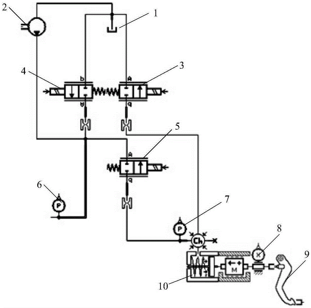
[0024] Such as figure 2 As shown, the inlet of the plunger pump 2 is connected to the outlet of the liquid storage tank 1, the brake master cylinder 10 is connected to the brake pedal 9, and the brake pedal 9 is provided with a displacement sensor 8 for detecting the displacement and acceleration of the brake pedal 9, and the brake The working chamber of the master cylinder 10 is respectively connected to the outlet of the plunger pump 2 and the inlet of the liquid storage tank 1. A drain valve 3 as a draining device is provided between the working chamber and the inlet of the liquid storage tank 1. The master cylinder pressure sensor 7 for the master cylinder pressure, and a liquid replenishment valve as a liquid replenishment device are arranged between the working chamber and the outlet of the plunger pump 2 . The reflux valve 4 used as a reflux device is respectively connected to the outlet of the plunger pump 2 and the inlet of the liquid storage tank 1, and the system p...


PUM


Abstract

The invention discloses a brake-by-wire and pedal-force feedback system and a braking method. In the braking process, a liquid infusion device cuts off a communication passage between a working cavity and an outlet of a plunger pump, so that a pedal-force control system and a system-pressure control system are totally separated each other; therefore, the dependence of pedal feedback force on the system pressure is avoided, namely the main cylinder pressure and the system pressure are separately controlled; the phenomenon that when ABS braking is performed, the fluctuation of the system pressure leads to the fluctuation of the main cylinder pressure, and the pedal feedback force fluctuates is avoided, so that the independent control of pedal feedback force is realized; a main braking cylinder is simplified into a single-end structure, so that the processing difficulty of a complicated main braking cylinder is reduced, and the leaking problem of the complicated main braking cylinder is solved. When brake-by-wire is failed, braking liquid in the working cavity of the main braking cylinder passes through the liquid infusion device and then is applied on a braking wheel cylinder, so that standby brake of a vehicle is realized.

Description

technical field [0001] The invention relates to a brake-by-wire system, in particular to a brake-by-wire system and a pedal force feedback system and a braking method in which a pedal force control system and a system pressure control system are isolated from each other. Background technique [0002] Existing brake-by-wire systems, such as electronic hydraulic control systems, use an electronic brake pedal, but the brake pressure is provided by a plunger pump driven by a motor, and a high-pressure accumulator is used to store pressure, and the backup brake system More isolation solenoid valves are used in the system, and the whole system has more components and higher cost. In addition, in the existing braking system, the brake master cylinder is usually divided into a working chamber and a liquid replenishing chamber, which has a complex structure, a long braking path, and a slow brake pressure response. Such as figure 1 As shown, the existing brake-by-wire and pedal forc...

Claims


Application Information

Patent Timeline
IPC IPC(8): B60T13/66
CPCB60T13/66
Inventor 刘长运潘劲吴志强
Owner ZHEJIANG WANXIANG PRECISION IND
Learn More