
Method for automatically identifying defect type of polyethylene electrofusion joint through ultrasonic phased array inspection

An ultrasonic phased array, electrofusion joint technology, applied in character and pattern recognition, analysis of solids using sonic/ultrasonic/infrasonic waves, instruments, etc., can solve problems such as inability to identify, high quality requirements for ultrasonic spectra, and reduce professional requirements. , The defect identification results are reliable and the amount of data is small.

Active Publication Date: 2016-01-20
ZHEJIANG UNIV
View PDF6 Cites 23 Cited by
  • Summary
  • Abstract
  • Description
  • Claims
  • Application Information

AI Technical Summary

Problems solved by technology

Because this method adds and sums all column level signals for normalization processing, it ignores a large amount of useful information in the image, and has high requirements for the quality of the ultrasonic atlas, and can only realize the identification of a single defect of cold welding, while for the background noise Spectra that are larger, or contain other defects, cannot be identified
At present, there is no convenient and reliable automatic defect recognition technology for ultrasonic phased array images of polyethylene pipe electrofusion joints at home and abroad.

Method used

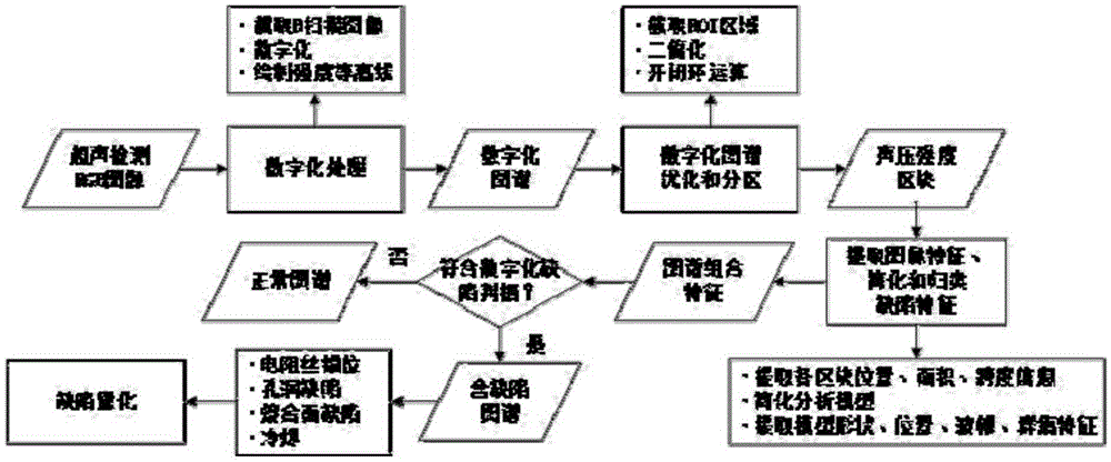

Image

  • Method for automatically identifying defect type of polyethylene electrofusion joint through ultrasonic phased array inspection
  • Method for automatically identifying defect type of polyethylene electrofusion joint through ultrasonic phased array inspection
  • Method for automatically identifying defect type of polyethylene electrofusion joint through ultrasonic phased array inspection

Examples


specific Embodiment example 1

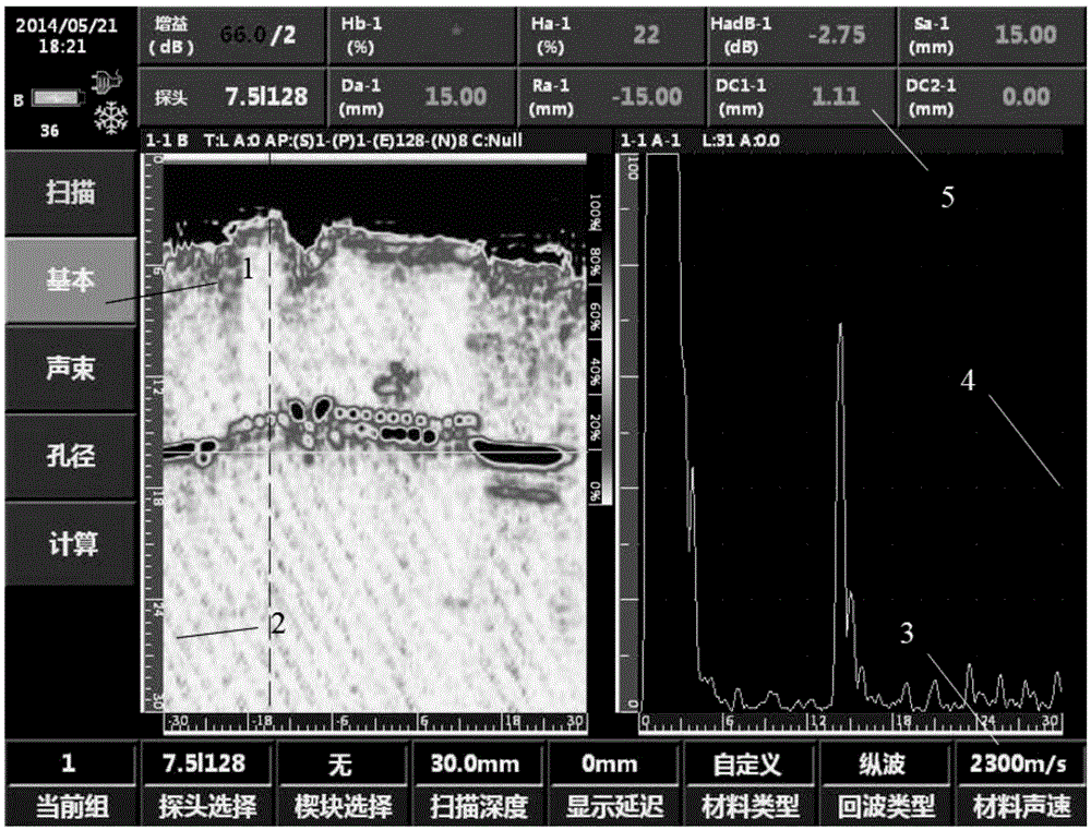
[0108] According to GB / T29461-2012, the ultrasonic phased array inspection is carried out on the normal and non-defective electrofusion joints, and the output ultrasonic images are as follows: figure 2 shown. Prior to the safety assessment of the EF joint according to GB / T29460-2012, defect identification is first required. The specific steps are:

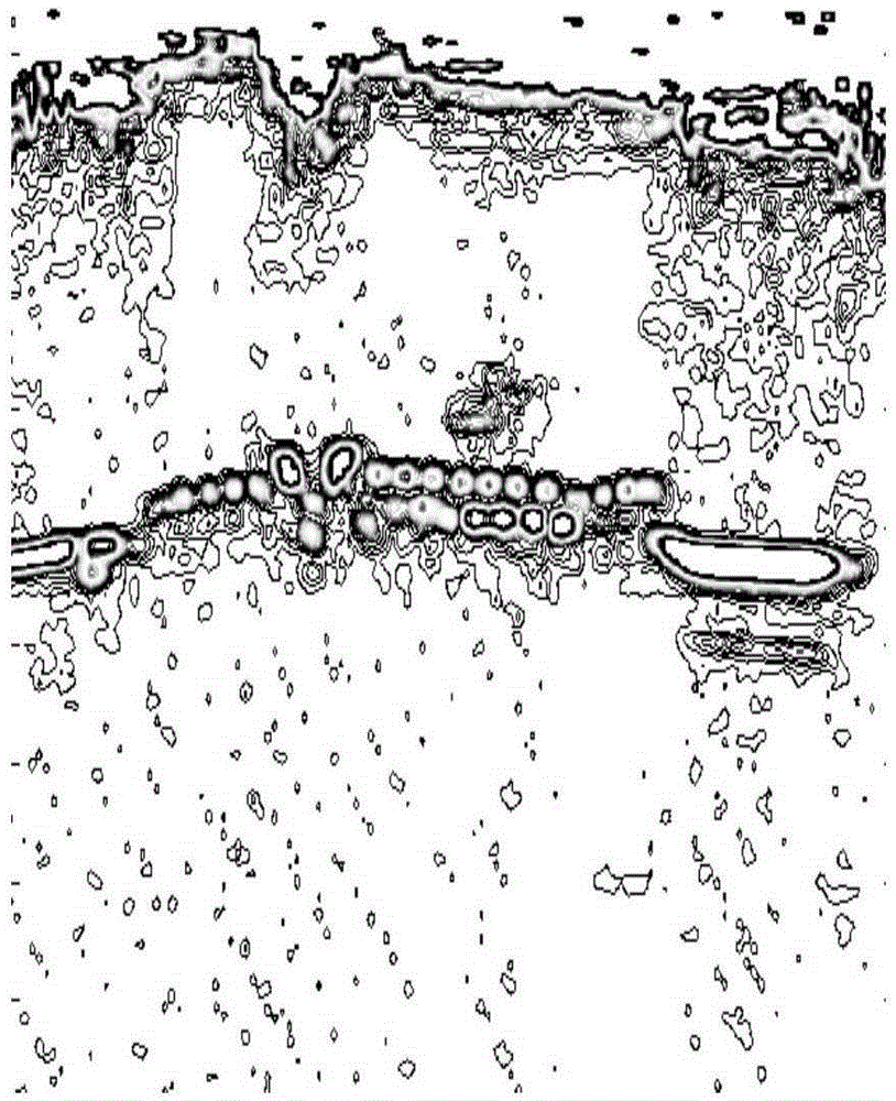
[0109] (1) Digitization of ultrasound atlas. Extract the ultrasonic atlas B-scan image 2 (fixed size 407*312); establish a one-to-one correspondence between the RGB value of the image and the sound pressure intensity, and obtain the R, G, and B curves corresponding to the sound pressure intensity according to the standard color bar interpolation results, Use the linear regression method to fit the three piecewise linear functions of the corresponding curves, use the weight method to determine the calculation formula of the corresponding intensity of different pixels, and finally obtain a two-dimensional matrix; use the RGB value...


PUM


Abstract

The invention relates to the welding joint defect identification technology and aims to provide a method for automatically identifying a defect type of a polyethylene electrofusion joint through ultrasonic phased array inspection. The method comprises steps as follows: the polyethylene electrofusion joint is subjected to phased array inspection by ultrasonic equipment, an ultrasonic phased array inspection map is output, and a two-dimensional real-time scanning image is captured for digital processing; a graphic feature is extracted after optimization and partition, and defect features are simplified and classified; an automatic defect identification criterion is established, the defect type is determined, and quantitative information is determined according to a specific defect characterization rule. According to the method, the defect type is automatically identified by analysis software, and the technical problem about automatic connection of ultrasonic inspection and safety assessment of the polyethylene electrofusion joint is solved; a two-dimensional matrix containing defect information is directly processed, the data size is small, the identification precision is high, and the identification efficiency is high; interference caused by human factors is avoided, so that the defect identification result is more reliable, the assessment result is more objective, and the method can be used for performing automatic identification and quantitative analysis on various irregular typical defects.

Description

technical field [0001] The invention relates to a welding joint defect identification technology. More specifically, the present invention relates to an automatic recognition method for detecting defect types of polyethylene electrofusion joints based on pattern recognition ultrasonic phased array. Background technique [0002] Electrofusion welding is one of the most important welding methods for polyethylene gas pipelines. In the process of electrofusion welding of polyethylene pipes, due to many factors such as joint assembly quality, welding process, cleanliness of joint surface, welding equipment and equipment, welding personnel, welding environment, etc., various defects are prone to occur in welded joints, and the welding quality is difficult. Get a reliable guarantee that the welded joint becomes the weak link of the polyethylene piping system. Electrofusion welded joints are prone to defects such as cold welding, resistance wire dislocation, and fusion surface inc...

Claims


Application Information

Patent Timeline
IPC IPC(8): G01N29/06G06K9/64
CPCG01N29/06B29C66/71B29C66/73921B29C65/8292B29C65/34B29C66/5229G06V10/20B29K2023/06
Inventor 施建峰聂新宇郭伟灿侯东圣郑津洋
Owner ZHEJIANG UNIV
Learn More