Low-g micromechanical acceleration latching switch

A micro-mechanical and acceleration technology, applied in electrical switches, contacts, electrical components, etc., can solve the problems that contacts are easily affected by external shock or vibration, easily interfered by the external environment, and difficult to meet the requirements of use. Convenient blocking threshold, wide threshold range, beneficial effect of structure release

Active Publication Date: 2016-01-13
CHONGQING UNIV
View PDF5 Cites 2 Cited by
  • Summary
  • Abstract
  • Description
  • Claims
  • Application Information

AI Technical Summary

Problems solved by technology

Although the traditional bump switch can provide an instantaneous conduction signal, the contact time of the switch is short, the contact is unstable, and it is easily disturbed by the external environment, which greatly limits its application range
The micromechanical latch switch can provide a permanent closing signal, but the mass block needs to overcome a large external force to realize the latch during the motion process, and the general threshold is as high as several thousand g, which is difficult to meet the use requirements in the low acceleration environment
For example, the micromechanical latching switch (A High-GAccelerationLatchingSwitchWithIntegratedNormally-Open / ClosePathsIndependenttotheProof-mass, IEEESENSORS, 2010, Conference) developed by Guo Zhongyang of Peking University and others has a closing threshold of 5000g, and due to the limitation of structural design, the folded beam occupies a large space, making this structure unsuitable for low-g latch switching
Another problem encountered in micromechanical latch switches is that the contact resistance is large, and the contacts are easily affected by external shock or vibration, and the contact reliability is low

Method used


Image

  • Low-g micromechanical acceleration latching switch
  • Low-g micromechanical acceleration latching switch
  • Low-g micromechanical acceleration latching switch

Examples


Embodiment Construction

[0032] Preferred embodiments of the present invention are described in detail below. For the experimental methods that do not specify specific conditions in the examples, usually follow the conventional conditions or the conditions suggested by the manufacturer.

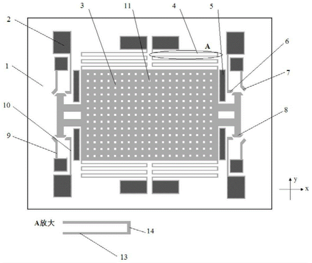
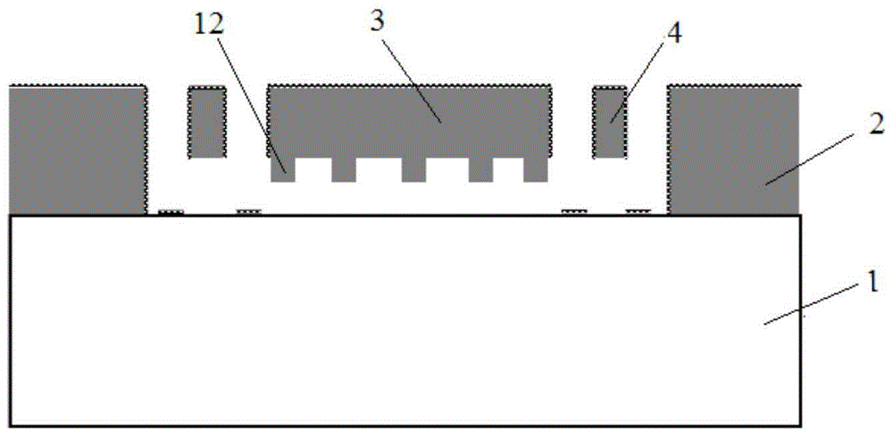
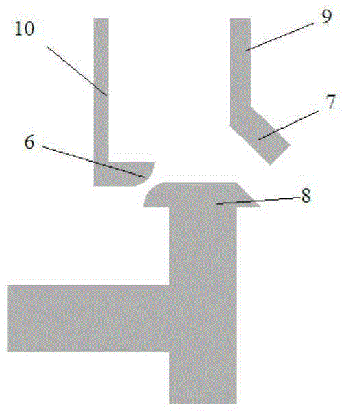
[0033] Wherein, the components represented by each reference numeral are as follows: 1-insulating substrate; 2-anchor point; 3-proof mass block; 4-proof mass block support beam; 5-overload protection structure; Induction contact; 8-moving contact; 9-induction contact support beam; 10-side contact support beam; 11-mass microhole; 12-mass microcolumn; 14 - proof mass support beam short beam.

[0034] The micro-mechanical acceleration switch of the present invention includes an insulating substrate, an anchor point, a contact, a disturbance beam (a contact support beam and a detection mass support beam), a detection mass and an overload protection structure.

[0035] Such as figure 1 As shown, the horizontal directio...


PUM


Abstract

The invention discloses a low-g micromechanical acceleration latching switch. The low-g micromechanical acceleration latching switch comprises an insulation substrate, a detection mass block, a plurality of anchor points, a plurality of contacts, a plurality of contact support beams, a plurality of detection mass block support beams and a plurality of overload protection structures; and the anchor points, the contacts, the contact support beams, the detection mass block support beams and the overload protection structures are symmetrically distributed relative to the X axis and the Y axis of the insulation substrate. The movable contacts of the micromechanical switch adopt hemispherical and wedge-shaped composite structures and form line contacts with side contacts, and energy loss in the motion process is reduced; the movable contacts form face contacts with the induction contacts, contact resistance values are reduced, and contact reliability is improved; the detection mass block, the flexible beams, the contacts and the anchor points are distributed in a completely axisymmetric manner, and bidirectional latching in plus or minus Y directions can be achieved; the detection mass block support beams are symmetrically distributed on two sides of the detection mass block, the structural layout is reasonable, and low-g latching is easy to achieve; and, through adjustments of gaps between the detection mass block, the flexible beams and the contacts, a latching threshold can be convenient to adjust, and the threshold scope is wide.

Description

technical field [0001] The invention belongs to the technical field of micro-electro-mechanical systems, and in particular relates to a low-g value micro-mechanical acceleration latch switch. Background technique [0002] With the development of MEMS (Micro-Electro-Mechanical Systems, micro-electro-mechanical systems) technology, micro-acceleration switches based on MEMS technology have the advantages of small size, light weight, low cost, low power consumption, high isolation, and anti-electromagnetic interference. It has significant advantages, and has extensive and important application requirements in the fields of automobile airbags, transportation process monitoring, impact records, and fuze safety insurance agencies. The extensiveness and complexity of the application environment put forward high reliability, high stability and high performance requirements for the micro acceleration switch. Although the traditional bump switch can provide an instantaneous conduction...

Claims


Application Information

Patent Timeline
Patent Type & Authority Applications(China)
IPC IPC(8): H01H35/14H01H1/00
CPCH01H1/0036H01H35/14
Inventor 李东玲尚正国温志渝彭迎春佘引
Owner CHONGQING UNIV
Why Eureka
Try Eureka