
a solar converter

A converter and solar energy technology, applied in the field of solar energy utilization, can solve the problems of slow heat collection rate, low heat transfer efficiency and large heat dissipation loss of solar collectors, so as to achieve small heat dissipation loss, high heat transfer efficiency and safety. high effect

Active Publication Date: 2018-01-16
丁海平
View PDF9 Cites 0 Cited by
  • Summary
  • Abstract
  • Description
  • Claims
  • Application Information

AI Technical Summary

Problems solved by technology

[0004] The purpose of the present invention is to provide a solar energy converter to solve the common problems of solar heat collectors in the prior art that the heat collection rate is slow, the heat transfer efficiency is not high, the heat dissipation loss during heat conduction is large, and the safety is poor. technical issues

Method used


Image

  • a solar converter
  • a solar converter
  • a solar converter

Examples


Embodiment 1

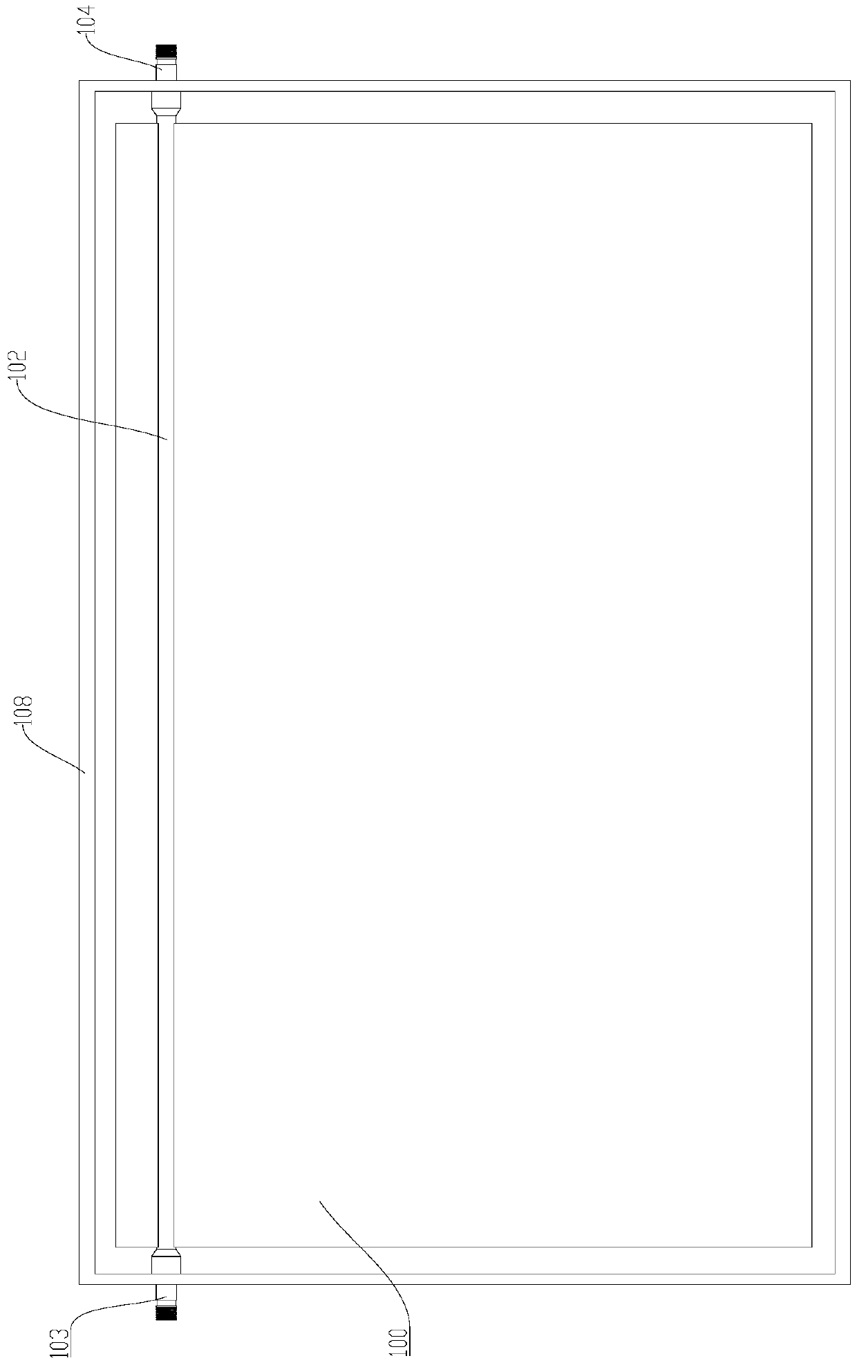
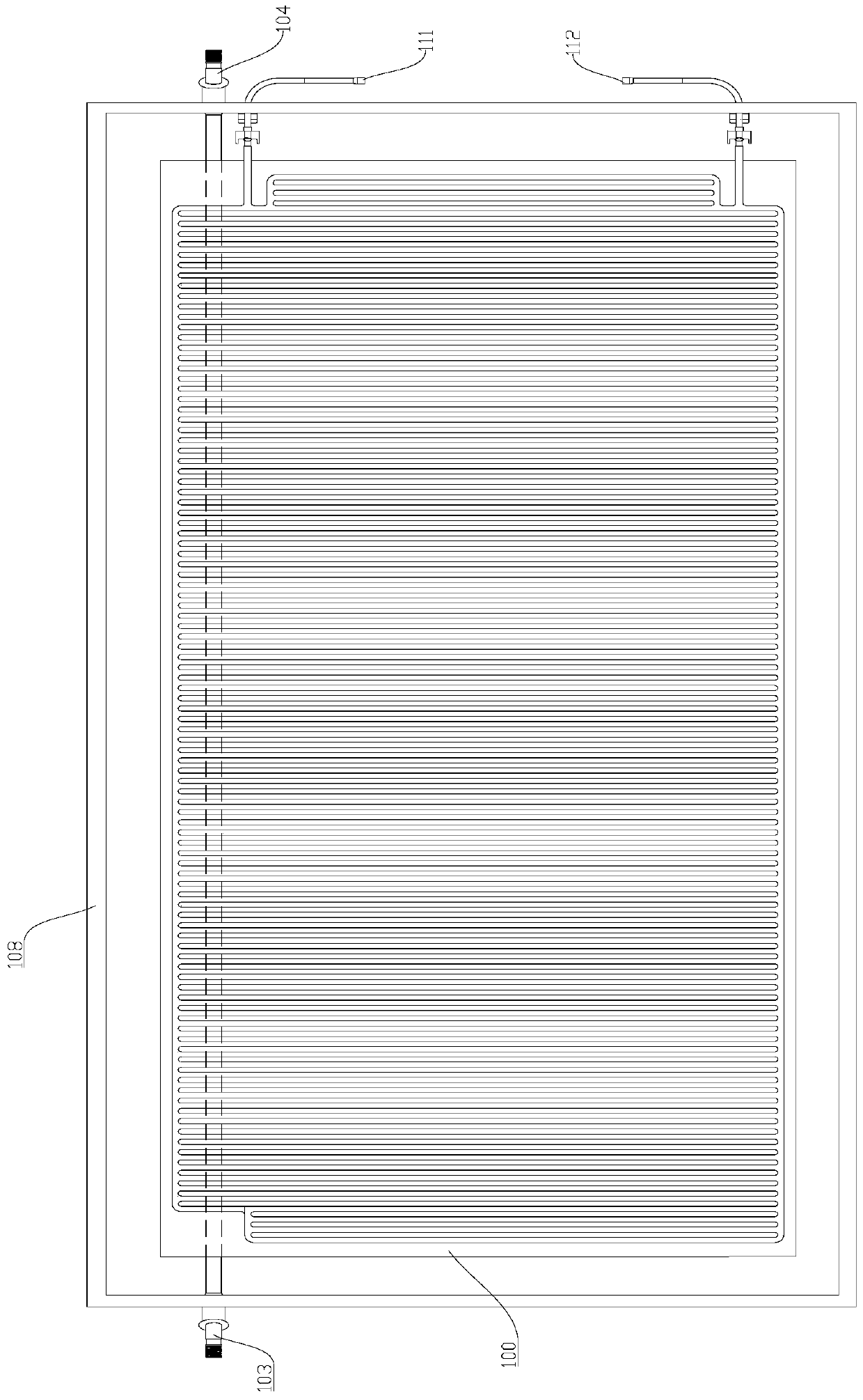
[0032] see figure 1 with figure 2 As shown, Embodiment 1 of the present invention provides a solar energy converter, including a heat collector plate core 100 and a heat exchange flow pipe 102; the heat collector plate core 100 includes a first panel 101, and the first panel 101 is a flat micro heat pipe; The first panel 101 is connected to the heat exchange flow pipe 102, and the heat exchange flow pipe 102 is located at the upper end of the first panel 101. Specifically, the first panel 101 is provided with a limiting groove, and the heat exchange flow pipe 102 is engaged. In the limit groove, on the one hand, the movement of the heat exchange flow pipe 102 can be restricted, and on the other hand, the outer surface of the heat exchange flow pipe 102 can be in close contact with the first panel 101, increasing the contact between the two area, thereby increasing the heat conduction efficiency; the two ends of the heat exchange channel tube 102 are the water inlet 103 and t...

Embodiment 2

[0040] see image 3 with Figure 4As shown, Embodiment 2 of the present invention provides a solar energy converter, including a heat collector plate core 100 and a heat exchange flow pipe 102; the heat collector plate core 100 includes a first panel 101, and the first panel 101 is a flat micro heat pipe; The first panel 101 is connected with the heat exchange flow pipe 102, and the heat exchange flow pipe 102 is located at the upper end of the first panel 101; the two ends of the heat exchange flow pipe 102 are water inlet 103 and water outlet 104 respectively.

[0041] In the second embodiment, the solar energy converter also includes a second panel 109, and the second panel 109 is a flat micro heat pipe; the edge of the first panel 101 is sealed with the edge of the second panel 109, and the first panel 101 and the second panel 109 A plurality of liquid flow channels 110 are arranged between them, and the plurality of liquid flow channels 110 communicate with each other; t...


PUM


Abstract

The invention relates to the technical field of utilization of solar energy and particularly relates to a solar energy converter. The solar energy converter comprises a heat collection plate core and a heat exchange runner pipe, wherein the heat collection plate core comprises a first panel; the first panel is a flat-plate type micro heat pipe and is connected with the heat exchange runner pipe; the heat exchange runner pipe is arranged at the upper end of the first panel; a water inlet and a water outlet are formed in two ends of the heat exchange runner pipe. Through the solar energy converter, the flat-plate type micro heat pipe is used as a heat absorption conductor; the heat collection velocity is increased; the solar energy converter is high in heat transfer efficiency, low in heat dissipation loss in the heat conduction process and high in safety.

Description

technical field [0001] The invention relates to the technical field of solar energy utilization, in particular to a solar energy converter. Background technique [0002] Solar energy is generated by the hydrogen-helium fusion of hydrogen atoms inside the sun and releases huge nuclear energy, which is the radiant energy from the sun. Most of the energy required by human beings comes directly or indirectly from the sun. Plants release oxygen and absorb carbon dioxide through photosynthesis, and convert solar energy into chemical energy and store it in plants. Fossil fuels such as coal, oil, and natural gas are also primary energy sources that evolved from ancient animals and plants buried underground over a long geological period. The energy contained in the earth itself usually refers to the energy related to the heat energy inside the earth and the energy related to the nuclear reaction. With fossil fuels decreasing day by day, solar energy has become an important part of...

Claims


Application Information

Patent Timeline
Patent Type & Authority Patents(China)
IPC IPC(8): F24S10/95F24S80/52F24S80/65
CPCY02E10/44
Inventor 丁海平
Owner 丁海平
Learn More