Clinical body temperature monitoring early warning system for hospital departments

A monitoring system and technology for body temperature, applied in the field of medical devices, can solve problems such as occupancy of wards and the inability of thermometers to be real-time, and achieve the effect of facilitating changes in body temperature and improving convenience and accuracy.

Inactive Publication Date: 2016-01-13
WELL DIAGNOSTICS TECH INT CORP
View PDF6 Cites 2 Cited by
  • Summary
  • Abstract
  • Description
  • Claims
  • Application Information

AI Technical Summary

Problems solved by technology

[0004] The purpose of the present invention is to provide a clinical body temperature monitoring system to solve the problems that existing thermometers cannot measure body temperature continuously in real time and occupy special spaces in departments such as wards and nurses' desks due to too many instruments

Method used


Image

  • Clinical body temperature monitoring early warning system for hospital departments
  • Clinical body temperature monitoring early warning system for hospital departments

Examples


Embodiment 1

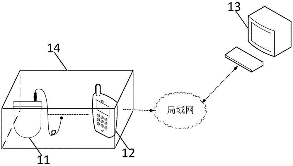
[0021] Please refer to figure 1 , which is a clinical body temperature monitoring system according to Embodiment 1 of the present invention. like figure 1 As shown, the clinical body temperature monitoring system provided by the present invention includes a first fixed terminal 11, at least one thermometer 12 and a mobile terminal 13; wherein, the at least one thermometer 12 is communicatively coupled to the mobile terminal 13 for The body temperature data of the user is collected and transmitted to the mobile terminal 13, and the mobile terminal 13 transmits the body temperature data to the first fixed terminal 11 through the local area network.

[0022] In the embodiment of the present invention, the clinical body temperature monitoring system further includes a storage box 14 , and the at least one thermometer 12 and / or the mobile terminal 13 are arranged in the storage box 14 . The storage box 14 is placed in the ward, that is to say, the at least one thermometer 12 and ...

Embodiment 2

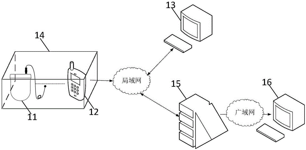
[0026] In the second embodiment, in addition to the device included in the first embodiment, the clinical body temperature monitoring system also includes a server 15, which receives the body temperature data transmitted by the mobile terminal 13 through the local area network, and sends the body temperature data through the local area network To the first fixed terminal 11 , the server 15 is set remotely relative to the first fixed terminal 11 , such as in a background computer room. The server 15 is used for integrating and processing the body temperature data collected by the at least one thermometer 12 . After the server 15 is introduced, a part of the functions of the first fixed terminal 11 is deployed on the server 15, which effectively reduces the resource requirements of the first fixed terminal 11 and the resulting software configuration and hardware volume , which reduces the volume of the first fixed terminal 11 that often needs to be arranged on the nurse's desk, ...


PUM


Abstract

The invention provides a clinical body temperature monitoring system, which comprises a fixed terminal, at least one thermometer and a mobile terminal, wherein the at least one thermometer is coupled with the mobile terminal in a communication way, and is used for collecting body temperature data of a user and transmitting the body temperature data of the user to the mobile terminal; and the mobile terminal transmits the body temperature data to the first fixed terminal through a local area network. The body temperature data collected by the thermometer can be transmitted to the mobile terminal in real time, so that a doctor/a nurse can know the body temperature change condition of a patient in time; and if the mobile terminal is arranged in a sickroom/at a sickbed, the convenience, the speed, the accuracy and the real-time performance of the system during the showing of the body temperature information of the patient to a sickroom inspection doctor/nurse can be improved. The temperature data collected by the thermometer can be transmitted to the first fixed terminal in real time; and if the first fixed terminal is arranged in a nurse desk, the system can show the body temperature information of the patient in a sickroom to the doctor/the nurse at the nurse desk, so that the doctor/the nurse can conveniently and timely master the body temperature change of the patient.

Description

technical field [0001] The invention relates to the technical field of medical devices, in particular to a clinical body temperature monitoring system. Background technique [0002] At present, most hospitals and specialized clinics use traditional mercury thermometers for body temperature measurement. During the measurement, they need to be in contact with the subject. The measurement time is about 5 minutes. Due to the possibility of cross-infection, it is necessary to check the thermometer before and after the measurement. For effective disinfection. For patients with poor cooperation such as coma, restlessness, and mental abnormalities, traditional thermometers cannot meet the clinical requirements, especially for comatose patients, the clinical requirement is to measure body temperature multiple times a day, which makes intensive care (ICU) nursing work extremely tedious , Nursing workload increased. [0003] In addition, patients in the intensive care unit (ICU) usua...

Claims


Application Information

Patent Timeline
Patent Type & Authority Applications(China)
IPC IPC(8): A61B5/01A61B5/00
Inventor 康宏
Owner WELL DIAGNOSTICS TECH INT CORP
Why Eureka
Try Eureka