
Control device used for improving PF value of DCM Buck PFC converter

A control device and converter technology, applied in output power conversion devices, high-efficiency power electronic conversion, climate sustainability, etc., can solve problems such as poor EMI differential mode performance, large switch conduction loss, and large inductor current peak value. , to achieve the effect of small output voltage ripple, small conduction loss, and reduced inductor current ripple

Active Publication Date: 2016-01-06
NANJING UNIV OF SCI & TECH
View PDF5 Cites 11 Cited by
  • Summary
  • Abstract
  • Description
  • Claims
  • Application Information

AI Technical Summary

Problems solved by technology

Although BoostPFC is an effective way to improve power factor and reduce current harmonics, the large loss at low-voltage input is also a bottleneck restricting its development, while BuckPFC makes the input and output voltages closer due to the Buck circuit’s own step-down characteristics. It can maintain high efficiency in the entire input voltage range. In addition, BuckPFC has the advantages of low output voltage, low common-mode EMI noise, no need for surge limiter and small main inductance, etc., which make BuckPFC gradually become a power factor correction A research hotspot in technology
[0004] The duty ratio of each switching cycle of the traditional DCMBuckPFC converter is the same, and the switching cycle is also constant. Although the control is simple, the inductance is small, and the diode has no reverse recovery problem, there are large peak currents of the inductor, poor EMI differential mode characteristics, and the conduction of the switching tube. Disadvantages of high pass loss and unoptimized efficiency

Method used


Image

  • Control device used for improving PF value of DCM Buck PFC converter
  • Control device used for improving PF value of DCM Buck PFC converter
  • Control device used for improving PF value of DCM Buck PFC converter

Examples


Embodiment Construction

[0024] The present invention will be described in further detail below in conjunction with the accompanying drawings and specific embodiments.

[0025] The working principle of 1DCMBuckPFC converter

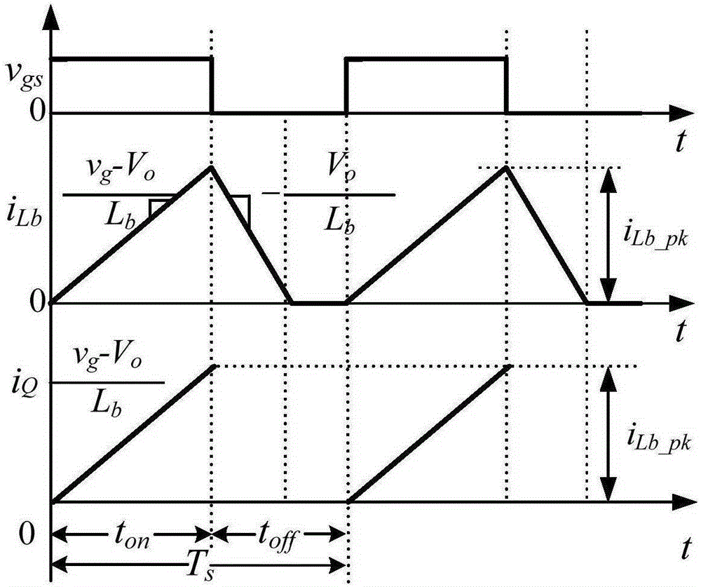
[0026] figure 1 It is the main circuit of BuckPFC converter.

[0027] For the convenience of analysis, the following assumptions are first made: 1. All devices are ideal components; 2. The output voltage ripple is very small compared with its DC value; 3. The switching frequency is much higher than the input voltage frequency.

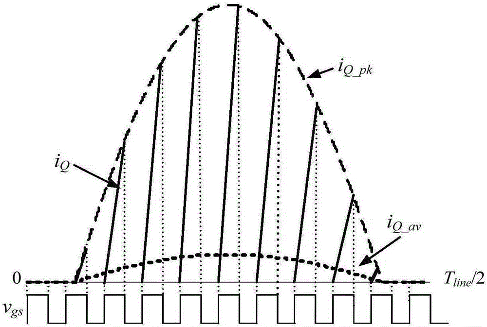
[0028] figure 2 The waveforms of switch tube current and inductor current in one switching cycle during DCM are given. When Q b When turned on, D b cutoff, the inductance L b The voltage across it is v g -V o , its current i Lb Start with zero and start with (v g -V o ) / L b The slope rises linearly, v g to the load and storage capacitor C o powered by. When Q b When shutting down, i Lb by D b freewheeling, at this time L b The voltage ...


PUM


Abstract

The invention discloses a control device used for improving the PF value of a DCM Buck PFC converter. The control device comprises a main power circuit and a control circuit. The main power circuit comprises an input voltage source vin, an EMI filter, a diode rectifier circuit RB, a Buck inductor Lb, a switch tube Qb, a diode Db, an output capacitor Co and a load RLd. The control circuit comprises an output voltage feedback control circuit, an input voltage feedforward circuit, a second multiplier and a sawtooth wave comparing and switch tube drive circuit. Input voltage feedforward and output voltage feedback are introduced, so that the duty cycle of the converter changes according to a certain rule in a power frequency cycle, and the PF value is improved to close to 1 in the AC input voltage range between 90V and 264V. The control device provided by the invention has the advantages of small output voltage ripple, small switch tube conduction loss, reduced required diode stress and the like.

Description

technical field [0001] The invention belongs to the technical field of AC-DC converters of electric energy conversion devices, in particular to a control device for improving the PF value of a DCMBuckPFC converter. Background technique [0002] A power factor correction (PowerFactorCorrection, PFC) converter can reduce input current harmonics and improve input power factor, and has been widely used. PFC converters are divided into active and passive methods. Compared with passive methods, the active method has the advantages of high input power factor, small size, and low cost. [0003] Since the development of active power factor correction technology (APFC) in the 1980s, scholars from various countries have conducted in-depth research from the perspectives of control strategy, circuit topology, and small signal modeling, and achieved a series of research results. For now, a new research focus of APFC technology is the research on PFC circuit topology. Theoretically, any ...

Claims


Application Information

Patent Timeline
IPC IPC(8): H02M1/42
CPCY02B70/10
Inventor 周旭峰姚凯李辉王祎王小平
Owner NANJING UNIV OF SCI & TECH
Learn More