Electro-optical-mechanical composite pulse laser beam combination device and method thereof
A pulsed laser and mechanical technology, applied in lasers, laser parts, circuits, etc., can solve problems such as limited response speed, achieve fast scanning speed, increase repetition frequency and average power, and large deflection.
- Summary
- Abstract
- Description
- Claims
- Application Information
AI Technical Summary
Problems solved by technology
Method used
Image

Examples
Embodiment 1
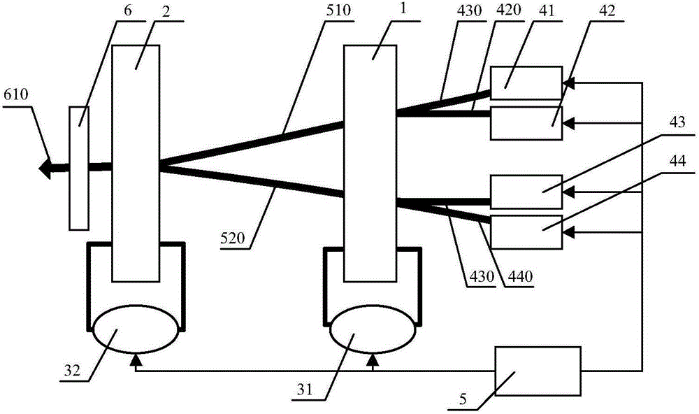
[0037] like figure 1 As shown, an electro-optic-mechanical composite pulsed laser beam combining device includes: an electro-optic deflector 1, a mechanical deflector 2, 2 driving circuits, 4 lasers, a synchronizing machine 5 and a laser collimating element 6, and a driving circuit 31 Cooperate with electro-optical deflector 1, drive circuit 32 cooperate with mechanical deflector 2, drive circuit 31, drive circuit 32 and all lasers are connected with synchronizer 5, and the output ports of the four lasers are opposite to electro-optical deflector 1 , the electro-optical deflector 1, the mechanical deflector 2 and the laser collimation element 6 are arranged in sequence along the transmission direction of the pulsed laser. The pulsed laser output from the laser can be a repetitive pulse or a single pulse, and can have different pulse shapes, pulse widths, wavelengths, spectral widths, chirp characteristics, amplitudes and other characteristics.
[0038] The electro-optical def...
Embodiment 2
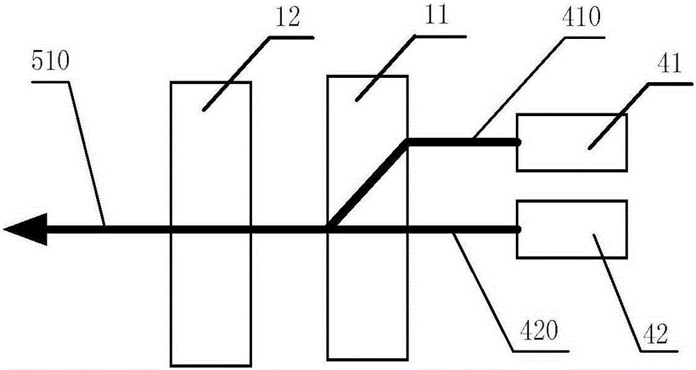
[0047] like figure 2 As shown, the same part as in Embodiment 1 will not be described in detail. The difference is that the electro-optic deflector 1 is a digitally coded electro-optic deflector, including an electro-optic crystal 12 and a birefringent crystal 11. and e light, that is, the pulse laser 410 output by the laser 41 is o light, and the pulse laser 420 output by the laser 42 is e light. After entering the birefringent crystal 11 from different positions, they can be combined into a beam of pulse laser. When one path of pulsed laser light passes through the electro-optic crystal 12, a half-wave voltage is applied to the electro-optic crystal 12 to change the polarization direction of the o-light or e-light (that is, to become all o-light or all e-light), and obtain the same electric polarization direction Photosynthetic beam laser laser 510 . In this embodiment, only the pulsed laser 410 and the pulsed laser 420 are used as an example for illustration, and the beam...
Embodiment 3
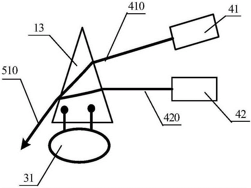
[0049] like image 3 As shown, the same part as in Embodiment 1 will not be described in detail. The difference is that the electro-optic deflector 1 is a prism electro-optic deflector, including an electro-optic crystal prism 13, and the electrode plates of the driving circuit 31 and the electro-optic crystal prism 13 are parallel to each other. The upper and lower bottom surfaces of the electro-optic crystal prism 13 are not limited to triangular prisms. Any prism with two parallel bottom surfaces and two non-parallel side surfaces can be used. The two non-parallel side surfaces are the incident surface and the outgoing surface. The electro-optic crystal prism 13 is a triangular prism, and the cross section of the triangular prism is an isosceles triangle. The pulsed laser light 410 output by the laser device 41 and the pulsed laser light 420 output by the laser device 42 are all incident on the side where a waist of the triangular prism is located. After passing through the ...
PUM
 Abstract
Description
Claims
Application Information
 - R&D
- Intellectual Property
- Life Sciences
- Materials
- Tech Scout
- Unparalleled Data Quality
- Higher Quality Content
- 60% Fewer Hallucinations
Browse by: Latest US Patents, China's latest patents, Technical Efficacy Thesaurus, Application Domain, Technology Topic, Popular Technical Reports.
© 2025 PatSnap. All rights reserved.Legal|Privacy policy|Modern Slavery Act Transparency Statement|Sitemap|About US| Contact US: help@patsnap.com