
A self-excited phase change thermal control cooling system

A heat dissipation system and phase change heat technology, applied in the direction of indirect heat exchangers, lighting and heating equipment, etc., can solve the problem that the condensate return method at the condensing end of the evaporation hot end needs to be improved, so as to enhance and condense the heat transfer effect and reduce the The effect of superheat and enhanced heat transfer capacity

Active Publication Date: 2017-04-19
FUJIAN CAS CERAMIC OPTOELECTRONICS TECH CO LTD
View PDF4 Cites 0 Cited by
  • Summary
  • Abstract
  • Description
  • Claims
  • Application Information

AI Technical Summary

Problems solved by technology

However, the heat exchange capacity of the evaporation hot end, the heat exchange capacity of the condensation end and the condensate return method still need to be improved.

Method used


Image

  • A self-excited phase change thermal control cooling system
  • A self-excited phase change thermal control cooling system
  • A self-excited phase change thermal control cooling system

Examples


Embodiment Construction

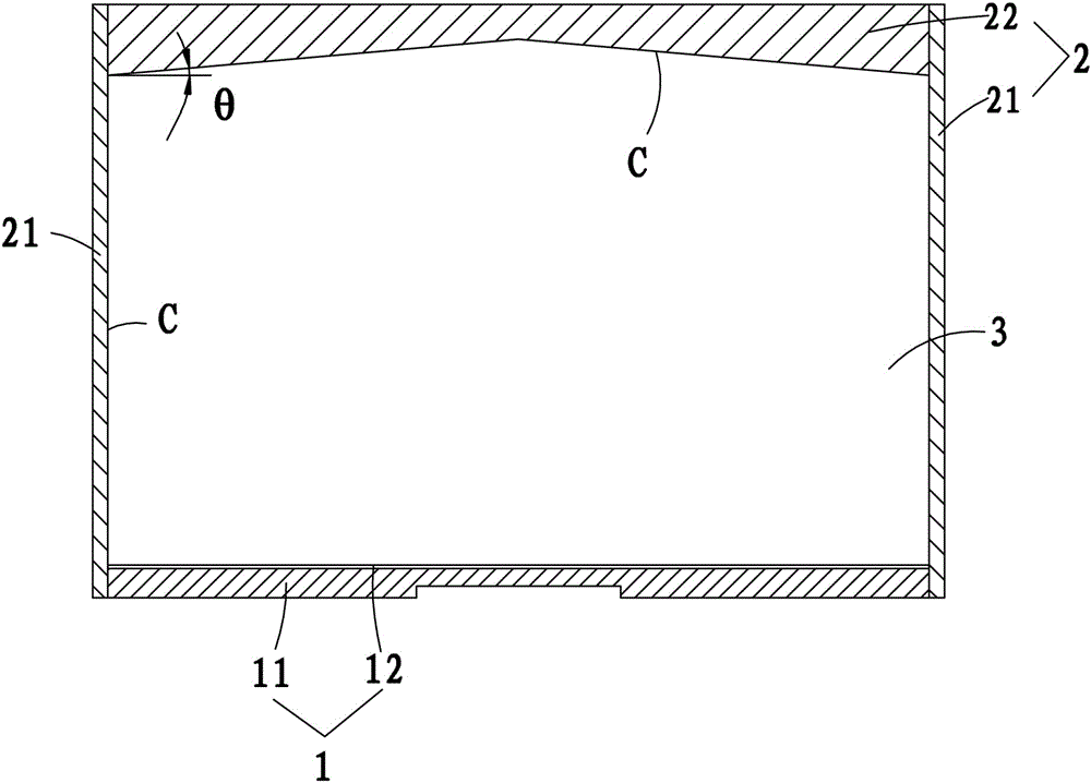
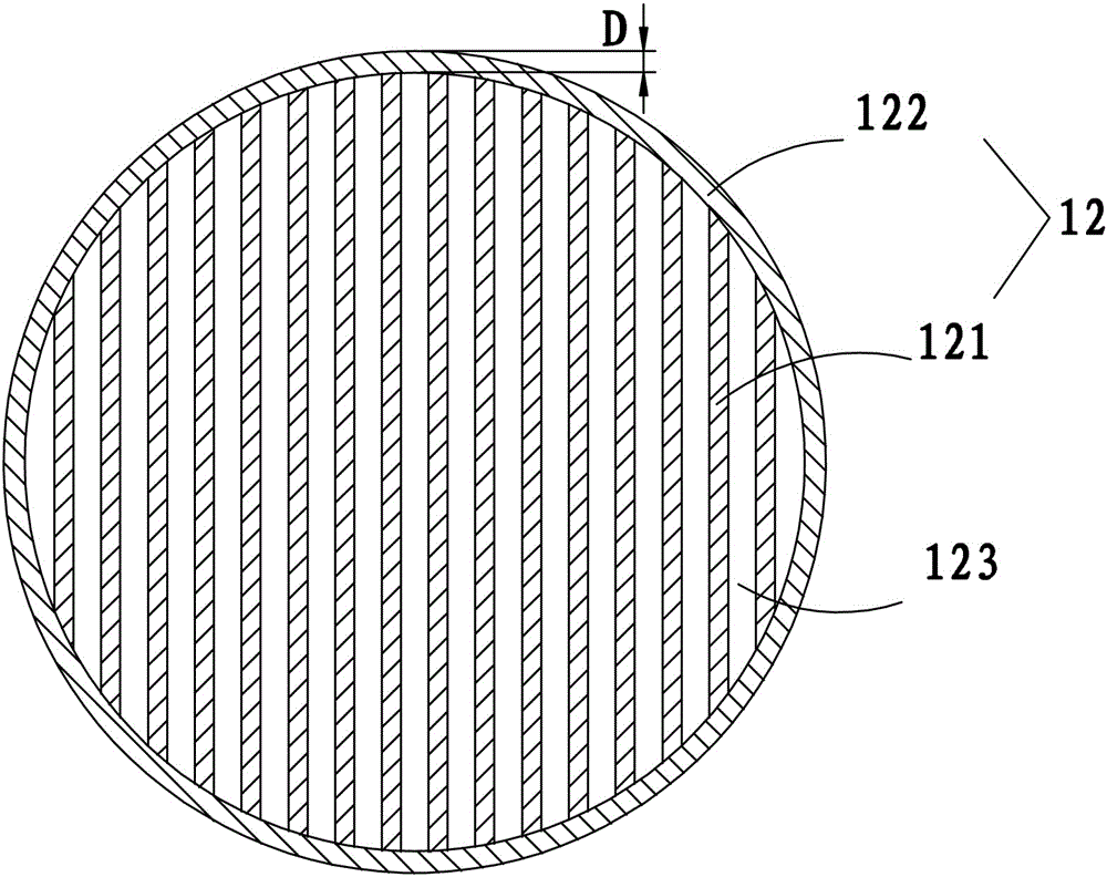
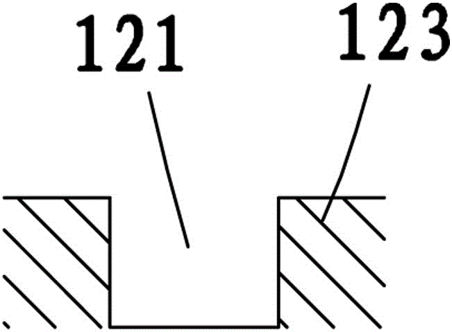
[0026] see Figure 1 to Figure 4 , the self-excited phase change thermal control and heat dissipation system of the present invention includes a heat extraction and evaporation module 1 and a condensation and heat dissipation module 2, and a seal for filling the working medium is formed between the heat extraction and evaporation module 1 and the condensation and heat dissipation module 2 The cavity 3, the heat-taking evaporation module 1 is located at one end of the closed cavity 3, and is composed of a heat-taking bottom plate 11 and an evaporation end surface microstructure 12, and the evaporation end surface microstructure 12 is arranged on the inner end surface of the heat-taking bottom plate 11, And it includes a capillary straight groove 121 and a liquid storage and supply groove ring 122 .

[0027] mainly as figure 2 As shown, the number of the capillary micro straight grooves 121 is multiple, and they are evenly distributed in parallel, and two adjacent capillary mi...


PUM


Abstract

The invention provides a self-excitation type phase change thermal control cooling system. The system comprises a heat taking evaporation module and a condensation cooling module, wherein a closed cavity for filling a working medium is formed therebetween; the heat taking evaporation module is positioned at one end part of the closed cavity, and consists of a heat taking baseplate and an evaporation end surface microstructure; and the evaporation end surface microstructure is arranged on an inner end surface of the heat taking baseplate. The system further comprises a capillary micro straight groove and a liquid accumulation and liquid supply groove ring; the condensation cooling module comprises a condensation side part and a condensation top plate; the condensation side part is positioned at the side edge of the closed cavity; the condensation top plate is positioned at the other end part of the closed cavity; and the inner end surfaces of the condensation side part and the condensation top plate are combined surfaces having a film liquid area and a dropping liquid area. As the capillary micro straight groove having high-strength phase change heat taking under fine scale is introduced, the critical heat flux density and the heat exchange coefficient are promoted, and the heat exchange capacity of a heat end is strengthened; and meanwhile, the drop type condensation is built at a condensation end for timely and effectively falling and updating drops, so that the condensation heat exchange effect is reinforced and promoted.

Description

technical field [0001] The invention relates to a self-exciting phase change thermal control cooling system. Background technique [0002] For thermal management under high heat flux density of tens of watts or even over a hundred watts per square centimeter, traditional air cooling technology needs to be equipped with large-area cooling fins, and the cooling module is bulky and heavy; although liquid cooling technology can meet the requirements to a certain extent, However, active technologies such as pumping pumps must be used, and there are specific requirements for pipeline construction and settings. Therefore, efficient heat transfer technology with appropriate dimensions must be sought. [0003] Phase change thermal control technology is a kind of high-efficiency heat transfer technology. It uses the principle of phase change. The working medium on the hot side is driven to evaporate through the heat absorption of the hot end, and the liquid-vapor phase change is gene...

Claims


Application Information

Patent Timeline
Patent Type & Authority Patents(China)
IPC IPC(8): F28D15/04
Inventor 陈明秦叶尚辉
Owner FUJIAN CAS CERAMIC OPTOELECTRONICS TECH CO LTD
Learn More