
Intelligent Nano Dynamic Centrifugal Rotary Separation Device

A rotary separation and nano technology, applied in grain processing and other directions, can solve the problems of stable separator and possible unfavorable operation, low separation efficiency, and inability to solve the problem of secondary entrainment of powder.

Active Publication Date: 2018-06-08
PUHLER GUANGDONG SMART NANO TECH CO LTD
View PDF7 Cites 0 Cited by
  • Summary
  • Abstract
  • Description
  • Claims
  • Application Information

AI Technical Summary

Problems solved by technology

Especially for separators operating at high temperature, high pressure, high speed and high flow rate, this brings great disadvantages to the stability and possible operation of the separator
In addition, the traditional separation technology cannot solve the problem of secondary entrainment of powder at all, which makes the separation efficiency low

Method used


Image

  • Intelligent Nano Dynamic Centrifugal Rotary Separation Device
  • Intelligent Nano Dynamic Centrifugal Rotary Separation Device

Examples


Embodiment Construction

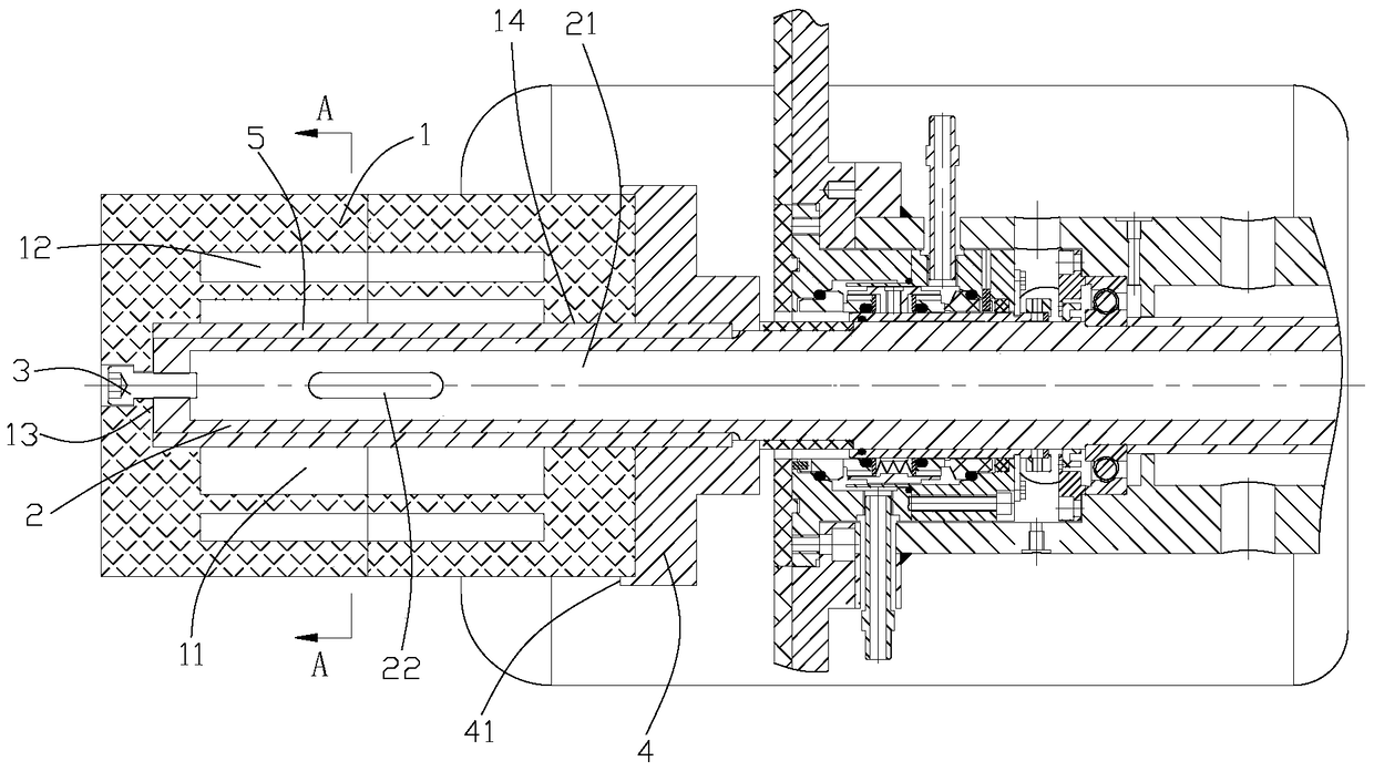
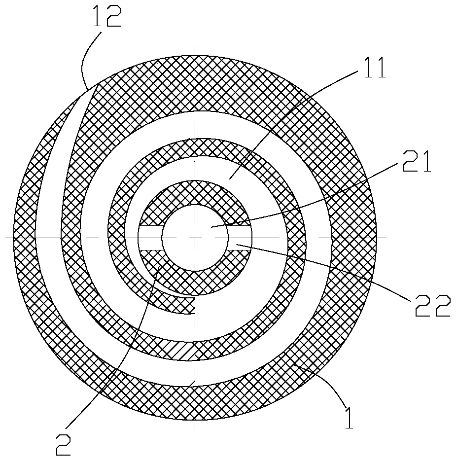
[0017] Combine below figure 1 , figure 2 The intelligent nanometer dynamic centrifugal rotating separation device of the present invention is introduced in detail, including a separation cylinder 1 arranged in the grinding barrel of a sand mill, a cavity 11 is formed inside the cylinder, and the axial ends of the cylinder are closed to drive the cylinder to rotate The hollow shaft 2 is axially inserted into the cavity, and the cavity communicates with the inner cavity 21 of the hollow shaft; preferably, the cavity communicates with the inner cavity of the hollow shaft through several discharge holes 22 arranged on the hollow shaft; A vortex 12 is provided inwardly from the outer wall of the cylinder, and the vortex communicates with the cavity. When the material is ground by the grinding medium in the grinding area of ​​the grinding cylinder, it gathers in the separation area under the action of the pressure in the grinding cylinder. The material in the separation area enter...


PUM


Abstract

The invention relates to the field of grinding equipment, in particular to an intelligent nanometer dynamic centrifugal rotary separation device, which includes a separation cylinder arranged in the grinding barrel of a sand mill, a cavity is formed inside the cylinder, and the two axial ends of the cylinder are Closed, the hollow shaft that drives the cylinder to rotate is axially inserted into the cavity, the cavity communicates with the inner cavity of the hollow shaft, and a vortex is opened inwardly from the outer wall of the cylinder, and the vortex communicates with the cavity. The separation device of the present invention completely abandons the structure of the existing screen separator, which allows the material to enter the inner cavity of the hollow shaft from the vortex to complete the discharge; since the separation device is driven by the hollow shaft to rotate, the strong centrifugal force generated during rotation Throw the grinding media, namely the grinding beads and the coarser material, to prevent the grinding beads from entering the inner cavity of the hollow shaft from the vortex; while the finer material can overcome the centrifugal force and enter the hollow shaft from the vortex under the pressure of the grinding cylinder. cavity, and then flow to the inner cavity of the hollow shaft to realize shaft discharge.

Description

technical field [0001] The invention relates to the technical field of solid-liquid separation during grinding of advanced materials and wet nanotechnology, in particular to a dynamic centrifugal separation device using microspheres for wet nanogrinding. Background technique [0002] my country's coal-fired power generation, cement, powder metallurgy, petroleum and natural gas, chemical industry, food, lithium titanate, lithium iron phosphate, paint, ink, flame retardant, photoelectric industry TFTLCD, Jet ink, magnetic materials, health products, biopharmaceuticals and Cell crushing, oxides, electronics industry, photoelectric industry, pharmaceutical biochemical industry, chemical fiber industry, building materials industry, metal industry, soap, leather, electronic ceramics, conductive paste, offset printing ink, textiles, biopharmaceuticals, inkjet ink, chip polishing fluid , cell crushing, cosmetics, inkjet ink, ceramic inkjet, metal nanomaterials, plastic materials, spec...

Claims


Application Information

Patent Timeline
Patent Type & Authority Patents(China)
IPC IPC(8): B02C17/18B02C23/08
Inventor 雷立猛
Owner PUHLER GUANGDONG SMART NANO TECH CO LTD
Learn More