
Granularity detection method

A detection method and particle size technology, applied in the direction of particle size analysis, particle and sedimentation analysis, measuring devices, etc., can solve the problems of no particle dispersion treatment, poor particle size authenticity, complex structure, etc., to achieve fast testing speed and easy operation. , the effect of testing a wide range

Inactive Publication Date: 2015-12-30
SUZHOU SABO IND DESIGN
View PDF6 Cites 7 Cited by
  • Summary
  • Abstract
  • Description
  • Claims
  • Application Information

AI Technical Summary

Problems solved by technology

The structure of the existing laser particle size analyzer is complicated, the operation is difficult, and the particles to be tested are not dispersed, resulting in poor authenticity of the particle size tested

Method used


Image

  • Granularity detection method
  • Granularity detection method
  • Granularity detection method

Examples


Embodiment Construction

[0025] In order to make the technical means, creative features, goals and effects achieved by the present invention easy to understand, the present invention will be further described below in conjunction with specific illustrations.

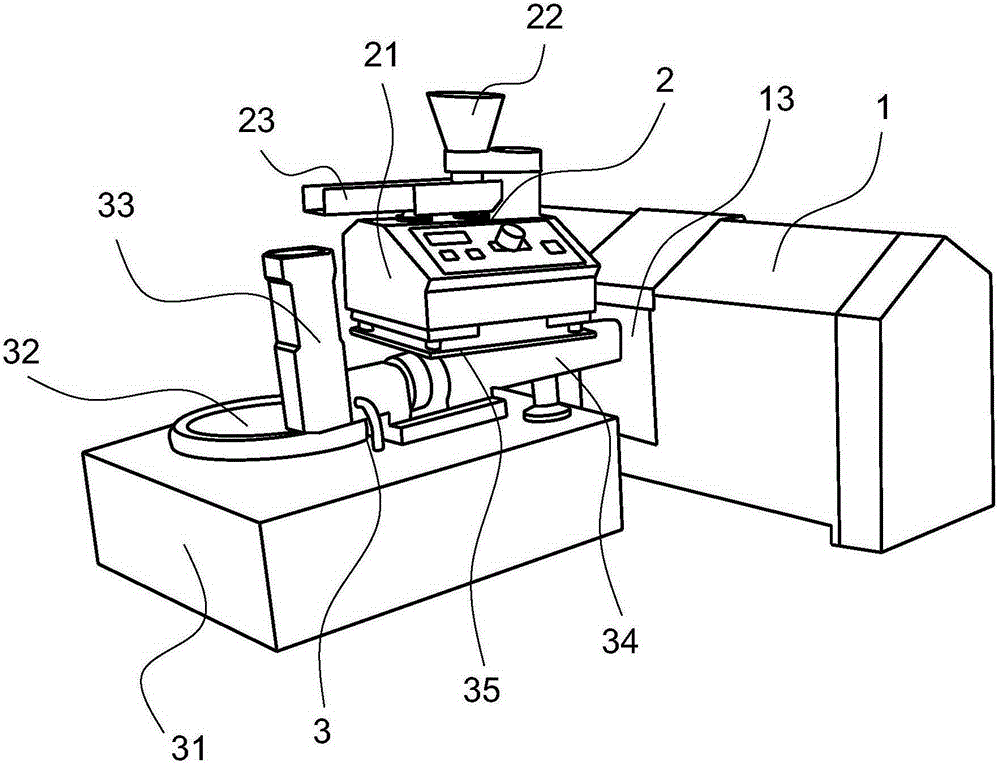
[0026] Figure 1-5 It is a structural schematic diagram of an embodiment of the present invention, which includes a laser diffraction system 1 , a sampling system 2 , a dispersion system 3 and a vacuum cleaner 4 .

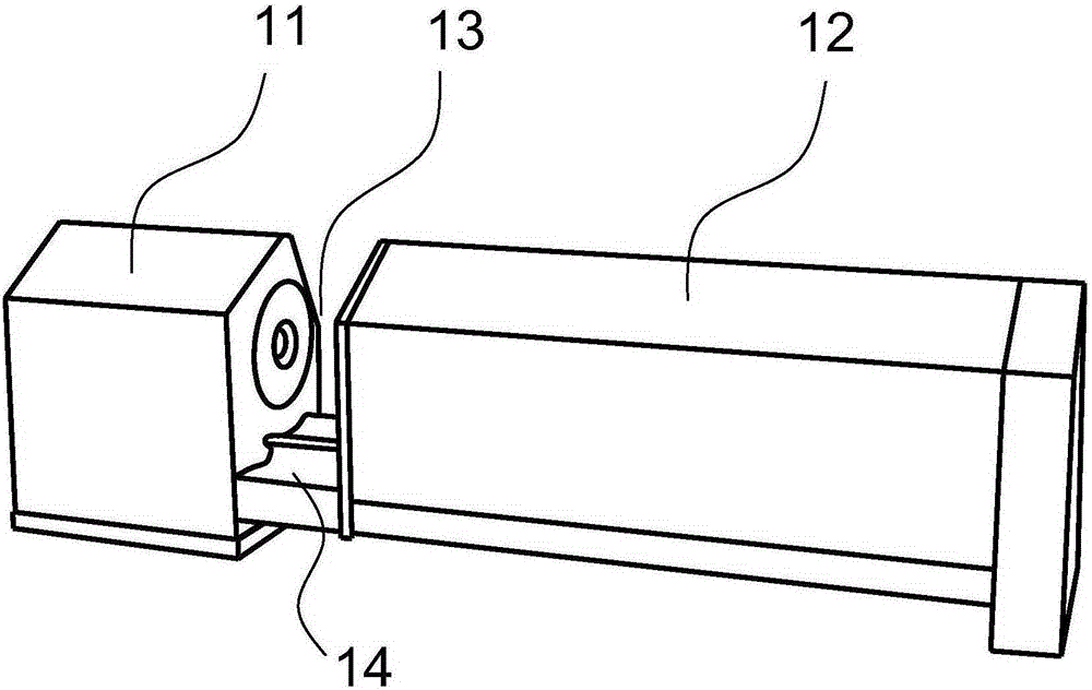
[0027] The laser diffraction system 1 comprises a laser system 11, a receiving system 12 and a test area 13. The test area 13 is located between the laser system 11 and the receiving system 12 and is an open area. There is a base 14 under the test area 13, the laser system 11 and the receiving system. The system 12 is respectively arranged on the two ends of the base 14, the laser system 11 and the receiving system 12 move relative to the base 14, so that the size of the test area 13 can be adjusted, and the below of the test area 13...


PUM


Abstract

The invention relates to a granularity detection method. The method particularly comprises the steps that a sample enters a sample tank from a feeding funnel, and the sample is vibrated into agglomerated granules under the vibration of the sample tank and continuously and stably fed into a cylindrical funnel; dispersing is conducted on the sample through a dispersion system, and the agglomerate granules are dispersed into single granules; the dispersed granule flow composed of the single granules passes through a testing area of a laser diffraction system under the suction effect of a dust collector, the laser diffraction system measures the granules passing through the testing area and transmits a detected result to a computer to be processed, and a result is obtained; the modular design is adopted, it is guaranteed that the obtained result is reliable and accurate, three modules are installed and combined to form a whole device, and moving and assembling are easy; the optics principles are adopted, detection and analysis of the granule distribution of emulsion, suspension, aerosols, powder aerosols, granules and the like are achieved in the fastest way, the testing speed is high, the testing range is wide, repeatability and authenticity are good, and operation is easy and convenient.

Description

technical field [0001] The invention relates to a particle size detection method. Background technique [0002] The laser particle size analyzer is an instrument that analyzes the particle size through the diffraction of particles or the spatial distribution of scattered light. It measures the particle size distribution based on the physical phenomenon that particles can cause laser light to scatter. Because the laser has good monochromaticity and strong directionality, a beam of parallel laser light will irradiate to infinite distance in an infinite space without hindrance, and there is little divergence during the propagation process. The existing laser particle size analyzer has a complicated structure and is difficult to operate, and the particles to be tested are not dispersed, resulting in poor authenticity of the measured particle size. Contents of the invention [0003] The technical problem solved by the present invention is to provide a particle size detection m...

Claims


Application Information

Patent Timeline
Patent Type & Authority Applications(China)
IPC IPC(8): G01N15/02
Inventor 丁会张苏陈力航
Owner SUZHOU SABO IND DESIGN
Learn More