
Rotary blade machine

A rotary vane, rotary vane technology, applied in rotary piston machines, rotary piston engines, rotary or swing piston engines, etc., can solve problems such as reducing compression ratio/expansion ratio, reducing mechanical efficiency, and large mechanical energy consumption. , to avoid friction and gap leakage, improve energy conversion efficiency, and reduce mechanical energy loss.

Inactive Publication Date: 2015-12-30
CHONGQING UNIV
View PDF11 Cites 7 Cited by
  • Summary
  • Abstract
  • Description
  • Claims
  • Application Information

AI Technical Summary

Problems solved by technology

However, there are problems with oil lubrication: due to the injection of lubricating oil, on the one hand, it occupies the effective volume of the volumetric fluid machine, thereby reducing the compression ratio / expansion ratio, thereby reducing the mechanical efficiency; on the other hand, the sliding vane compressor / The expander needs to add a lubricating oil cooling circulation pump, which not only increases the cost of the auxiliary equipment, but also increases the energy consumption required for the operation of the auxiliary equipment
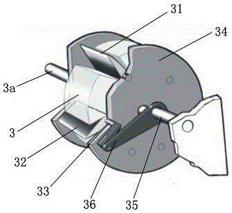
[0011] However, this hinged expander has the following problems: the actual structure of the hinged rotor is as image 3 As shown, on the outside of the cover plate 34, a link mechanism 36 is arranged between each hinge shaft 33 and the bearing seat ( image 3 There are six linkage mechanisms shown, and the hinge shaft plus the connecting rod connection shaft has twelve shafts)
The structure is complex. After the hinge rotor rotates, it drives all the linkage mechanisms 36 to move, which consumes a lot of mechanical energy. Since the hinge rotor is equipped with a cover plate 34, the rotation of the cover plate also produces huge friction on the inner cylinder wall of the stator, further increasing the hinge. The mechanical energy loss of the type expander;
[0012] In addition, the hinged expander has poor sealing performance, which is mainly manifested in: 1. The gas enters the concave groove 32 and leaks through the gap at the bottom of the hinge blade; 2. The gas passes through the hinge shaft on the cover plate ( image 3 A total of six rotating shafts) the bearing gap leaks to the outside of the rotor cover plate, 3. The gas leaks to the outside of the cover plate through the gap between the top edge of the cover plate and the inner cylinder wall of the stator
These media leaks cause leak power
Therefore, the energy conversion efficiency of the hinged expander is still very low, and its energy conversion efficiency needs to be improved

Method used


Image

  • Rotary blade machine
  • Rotary blade machine
  • Rotary blade machine

Examples


Embodiment Construction

[0034] Below in conjunction with accompanying drawing and embodiment the present invention will be further described:

[0035] Such as Figure 4 As shown, the present invention includes a stator 1 and a rotary vane rotor 4, the rotary vane rotor 4 axis deviates from the axial center of the stator inner cylinder and is installed in the stator inner cylinder, and the rotary vane rotor 4 includes a rotor body 41, rotating blades 42 and regulating block 43;

[0036] Such as Figure 5 with Image 6 As shown, the circumferential surface of the rotor body 41 is provided with evenly distributed blade slots 41a in the axial direction, and the two sides corresponding to the bottom ends of the blade slots 41a are provided with adjusting block grooves 41b in the radial direction;

[0037] Such as Figure 7 with Figure 8 As shown, arc-shaped notches 42c are formed on both sides of the bottom end of the rotating blade 42, and the center of the arc-shaped notch 42c is provided with a b...


PUM


Abstract

The invention discloses a rotary blade machine, and particularly relates to an expander and / or compressor with rotary blades. The rotary blade machine comprises a stator and a rotary blade type rotor. The rotary blade type rotor is installed in a stator inner cylinder in the mode that the axis of the rotary blade type rotor deviates from the axis of the stator inner cylinder, and the rotary blade type rotor comprises a rotor body, the rotary blades and adjusting blocks; blade notches evenly distributed are formed in the circumferential face of the rotor body in the axial direction, and adjusting block grooves are formed in the two side faces corresponding to the bottom end of each blade notch in the radial direction; arc gaps are formed in the two sides of the bottom end of each rotary blade, and a blade rotating shaft is arranged in the center of each arc gap; semicircular parts matched with the arc gaps of the rotary blades are arranged at the tops of the adjusting blocks, shaft holes are formed in the centers of the semicircular parts, and screw via holes are formed in the tops of the adjusting blocks. The rotary blades are installed in the blade notches of the rotor body through matching of the blade rotating shafts and the shaft holes of the adjusting blocks, and the adjusting blocks are fixed into the adjusting block grooves of the rotor body through the screw via holes. The rotary blade machine has the advantages of being simple in structure, reducing energy consumption and improving energy conversion efficiency.

Description

technical field [0001] The invention belongs to a mechanical device that utilizes a fluid medium to realize energy conversion, and in particular relates to an expander or compressor with rotating blades. Background technique [0002] The expander and the compressor are named according to the different usage conditions or functions. The usage condition of the compressor is driven by power, and its function is to compress the low-pressure gas into a high-pressure gas; Obtain low-pressure gas and push the rotor to rotate, and its function is to output power outward. [0003] Expanders are generally divided into two categories according to their operating modes: one is an expander that can perform work on the outside at the speed of gas (such as a turbo expander), and the other is an expander that can perform work on the outside by expanding the gas in the variable volume of the equipment. Machine (such as: piston expander, screw expander, sliding vane expander, etc.). [0004...

Claims


Application Information

Patent Timeline
Patent Type & Authority Applications(China)
IPC IPC(8): F01C1/44F01C21/08F01C19/00F04C18/44F04C27/00
Inventor 巫山
Owner CHONGQING UNIV
Learn More