
A kind of steel flat angle welding method for ship hull structure

A technology of structural steel and welding methods, applied in welding equipment, arc welding equipment, manufacturing tools, etc., can solve the problems of low weld strength, unfavorable base metal corrosion protection, etc., to ensure welding quality, reduce ship construction period, eliminate Effect of Welding Stress

Active Publication Date: 2017-10-27
WUCHANG SHIPBUILDING IND
View PDF5 Cites 2 Cited by
  • Summary
  • Abstract
  • Description
  • Claims
  • Application Information

AI Technical Summary

Problems solved by technology

[0008] The invention provides a steel flat fillet welding method for hull structure, which solves the problems of low weld strength and unfavorable base metal anticorrosion existing in the existing steel flat fillet welding method for hull structure, so as to save more welding materials and electric energy and working hours, and easy to process, effectively reducing welding deformation

Method used


Image

  • A kind of steel flat angle welding method for ship hull structure
  • A kind of steel flat angle welding method for ship hull structure
  • A kind of steel flat angle welding method for ship hull structure

Examples


Embodiment 1

[0027] Embodiment 1, comprises the following steps:

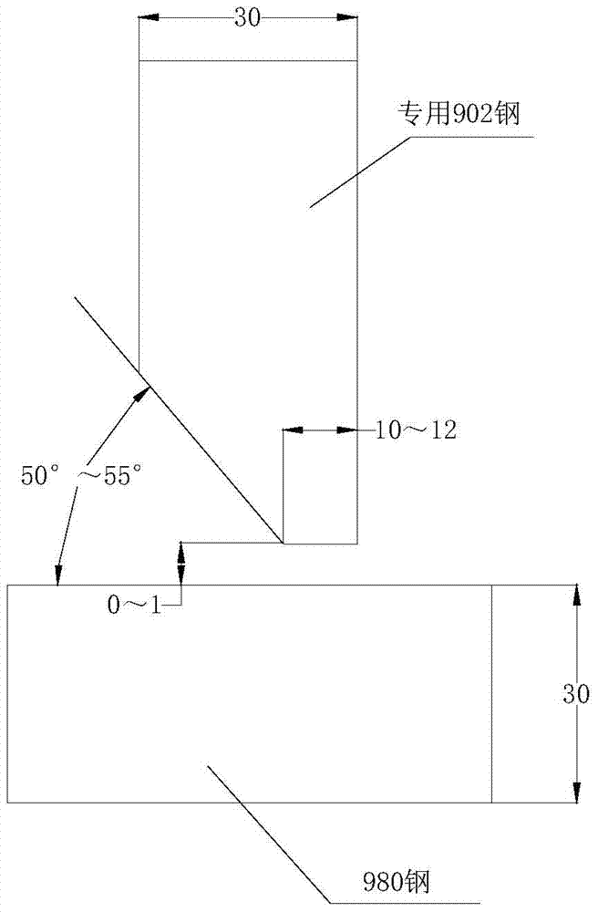
[0028] (1) Groove forming steps: such as figure 1 As shown, a single V-shaped bevel groove is formed on the corner joint of a special 902 steel workpiece with a thickness of 30mm, leaving a root of 10mm, and the angle of the bevel groove relative to the surface of the base part is 55°; The end face should remove water stains, oil stains, rust, hanging slag and other sundries that affect the welding quality;

[0029] (2) Preheating step: Corner joint the workpiece to be welded with the 30mm thick 980 steel base part to form a single V-shaped corner joint groove, the corner joint groove angle is 55°, and the angle joint groove gap is 0mm to 1mm; Then preheat the corner joint groove and the range of 150mm on both sides, and start welding when the preheating temperature reaches 130°C;

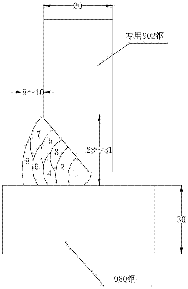
[0030] (3) Front welding step: as shown in Figure 2(A), 5 layers and 8 passes of manual arc welding are used to fill the bevel groove of the ...

Embodiment 2

[0035] Embodiment 2, is exactly the same as the step of embodiment 1, and difference is only in the process parameter in each step:

[0036] In the step of forming the bevel, the root is 12mm, and the bevel angle of the bevel is 50°;

[0037] In the preheating step, the corner joint groove angle is 50°, the corner joint groove gap is 0 mm to 1 mm, and the preheating temperature reaches 100 ° C to start welding;

[0038] In the front welding step, the temperature between passes is controlled at 100°C during welding.

[0039] In the post-welding treatment step of the front side, the heating temperature reaches 250°C, and the heat preservation time is 2 hours;

[0040] In the root cleaning step on the back side, the preheating temperature reaches 100°C;

[0041] In the back welding step, the temperature between the passes is controlled at 100°C during welding;

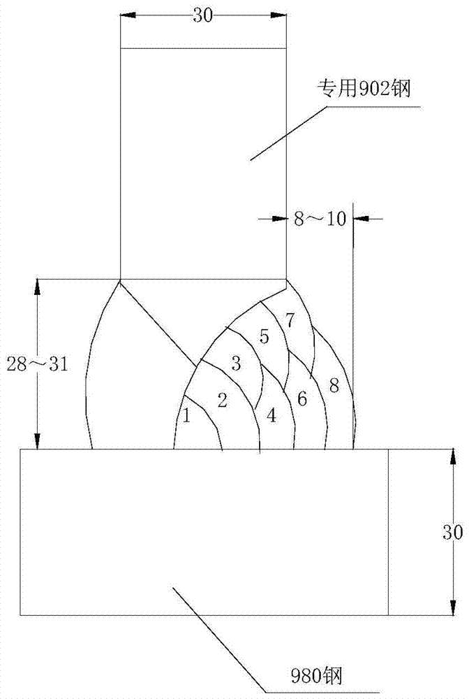
[0042] In the post-soldering treatment step of the back surface, the heating temperature reaches 250° C. and the tem...


PUM

PropertyMeasurementUnit
strengthaaaaaaaaaa

Abstract

The invention relates to a flat-angle welding method for hull structural steel, and belongs to welding methods for hull structural steel. The problems that an existing flat-angle welding method for hull structural steel is bad for base material corrosion prevention, and weld joints are low in strength are solved. The flat-angle welding method includes the steps of groove forming, preheating, front face welding, postweld treatment on the front face, back gouging, back face welding and postweld treatment on the back face. Machining is easy, welding deformation is effectively reduced, flat-angle welding for the hull structural steel is smoothly achieved and passes a weldability test and welding procedure qualification, labor efficiency can be improved, welding materials, electric energy and labor hour can be saved, the production cost is reduced, the shipbuilding cycle is shortened, and the blank of welding ship structural steel and forged steel in China is filled up.

Description

technical field [0001] The invention belongs to a welding method of steel for hull structure, and in particular relates to a welding method for flat fillet welding of steel for hull structure. Background technique [0002] Welding technology is one of the key technologies of modern shipbuilding engineering, and the quality of ship welding in hull construction is an important indicator for evaluating shipbuilding quality. Therefore, the advancement of welding technology is of great significance to promote the development of shipbuilding production. Internationally, high-strength steel welding technology has developed rapidly in terms of welding material composition and process design, and its application fields are also expanding. In the field of steel structure manufacturing involving special requirements and harsh working conditions (such as irradiation conditions), high-strength steel occupies an increasingly important position and has been widely used in ships, bridges, ...

Claims


Application Information

Patent Timeline
Patent Type & Authority Patents(China)
IPC IPC(8): B23K9/00B23K9/235B23K9/095
CPCB23K9/00B23K9/095B23K9/235B23K2103/04
Inventor 王波赵钦之
Owner WUCHANG SHIPBUILDING IND
Learn More