Scroll compressor

A technology for compressors and scroll disks, applied in the field of compressors, can solve problems such as difficult manufacturing, composite or two-stage scroll compressors that have not been widely developed, and reduce input loss, enhance compressor efficiency, and increase volume ratio Effect

Inactive Publication Date: 2015-12-23
LG ELECTRONICS INC
View PDF7 Cites 1 Cited by
  • Summary
  • Abstract
  • Description
  • Claims
  • Application Information

AI Technical Summary

Problems solved by technology

However, the scroll compressor should be formed such that the fixed scroll is engaged with the orbiting scroll, and thus is difficult to manufacture compared with other compressors, and as a result, compound or two-stage scroll compressors have not been widely developed

Method used


Image

  • Scroll compressor
  • Scroll compressor
  • Scroll compressor

Examples


Embodiment Construction

[0068] Hereinafter, a compressor according to the present disclosure will be described in detail with reference to embodiments shown in the accompanying drawings.

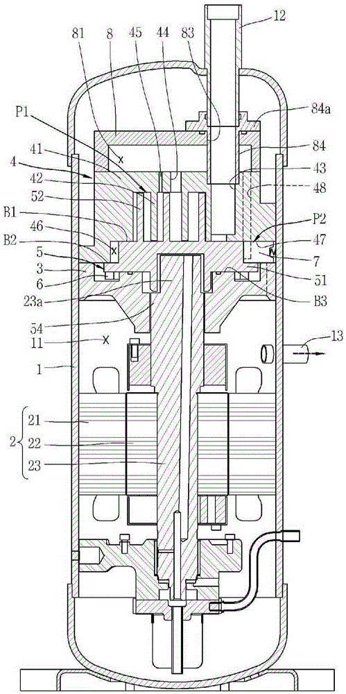
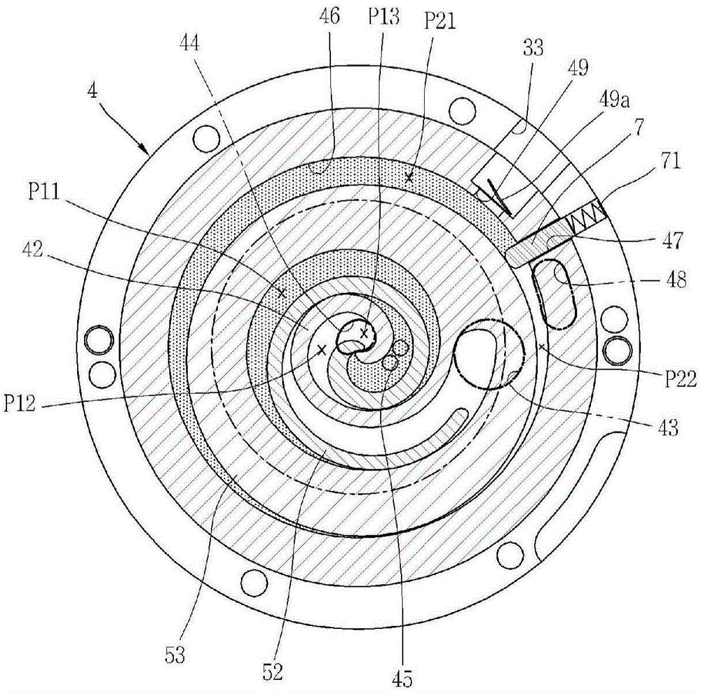
[0069] figure 1 To show a longitudinal sectional view of an example of a two-stage compressor according to the present disclosure, figure 2 to show the basis figure 1 An enlarged longitudinal sectional view of the compression unit in the two-stage compressor of , image 3 for along figure 2 A cross-sectional view of the line "I-I", Figure 4 For fixed scroll and orbiting scroll and according to figure 2 A perspective view of the compression unit detached, and Figure 5 to illustrate the basis of figure 1 Longitudinal cross-sectional view of the refrigerant suction and discharge paths in a two-stage compressor.

[0070] As described above, in the two-stage compressor according to the present disclosure, the driving motor 2 for generating a rotational force in the inner space 11 of the container 1 may be pr...


PUM


Abstract

A compressor according to the present disclosure may include a container; a drive motor provided in the container; a crankshaft coupled to a rotor of the drive motor; a first scroll coupled to the crankshaft to receive a rotational force of the drive motor to perform an orbiting movement; a second scroll coupled to the first scroll to form a first compression unit and a second compression unit along with the first scroll; and a vane provided in the first scroll or second scroll to be brought into contact with the other side scroll to form the second compression unit, wherein the first compression unit is carried out in a scroll compression mode and the second compression unit is carried out in a rotary compression mode.

Description

technical field [0001] The present disclosure relates to a compressor, and more particularly, to a two-stage compressor having a scroll-side compression unit and a rotation-side compression unit. Background technique [0002] Generally, a refrigerant compressor may be applied to a vapor compression refrigeration cycle (hereinafter, abbreviated as "refrigeration cycle") such as a refrigerator, an air conditioner, and the like. As for the refrigerant compressor, a constant speed compressor driven at a predetermined speed or an inverter compressor whose rotational speed is controlled is introduced. [0003] Refrigerant compressors can generally be classified into hermetic compressors and open compressors, in which a driving motor, which is an electric motor, and a compression unit operated by the driving motor are disposed together inside a hermetic case space, while in an open compressor, the drive motor is provided separately outside the casing. Hermetic compressors are mai...

Claims


Application Information

Patent Timeline
Patent Type & Authority Applications(China)
IPC IPC(8): F04C18/02F04C29/06
CPCF04C23/005F04C18/0215F04C18/0253F04C18/3564F04C23/008F04C29/0057F04C29/12F04C2240/56F05C2225/00
Inventor 崔允诚俞炳吉崔世宪金镇护裴哲稷李丙哲
Owner LG ELECTRONICS INC
Why Eureka
Try Eureka