On-site recovery system for leaking waste liquid

A waste liquid recovery and waste liquid collection technology, applied in liquid distribution, transportation or transfer devices, special distribution devices, packaging, etc., can solve the problems of physical health hazards of maintenance personnel, leakage of leakage, and easy failure of pumps. Avoid leakage of waste liquid, avoid the danger of explosion, and ensure the effect of continuity

Active Publication Date: 2015-12-23
LUXI CHEM GRP
View PDF6 Cites 1 Cited by
  • Summary
  • Abstract
  • Description
  • Claims
  • Application Information

AI Technical Summary

Problems solved by technology

[0002] The media involved in the production process of cyclohexanone mainly include flammable, toxic and volatile organic substances such as cyclohexane, cyclohexanol, cyclohexanone, and cyclohexene. In the recovery of traditional cyclohexanone waste liquid, Each sewage and deluge enters the underground tank through the recovery main pipeline. When the liquid level in the underground tank reaches a certain height, the pump is used to transport the waste liquid in the underground tank to the unit used or the waste liquid treatment place, but the pump is prone to failure. During the maintenance process of the pump, it is inevitable to produce leakage, irritating smell, pollute the environment, and bring harm to the health of post operators and maintenance personnel.
In addition, the environment of the underground tank in the traditional method is air, and the gas volatilized with the waste liquid is easy to form an explosive gas, which may cause an explosion

Method used


Image

  • On-site recovery system for leaking waste liquid
  • On-site recovery system for leaking waste liquid

Examples


Embodiment 1

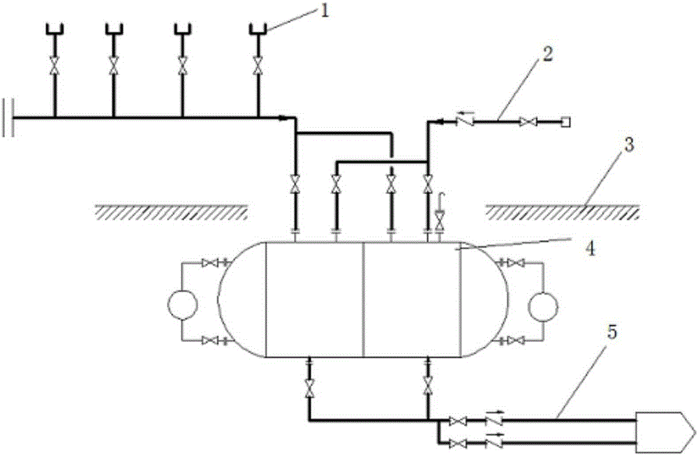
[0026] Such as figure 1 As shown, an on-site waste liquid recovery system includes a waste liquid recovery pipeline 1, a waste liquid collection tank 4, an inert gas pressurized pipeline 2, and a waste liquid delivery pipeline 5, wherein the waste liquid recovery pipeline 1 and the inert gas The pressurized pipelines 2 are all connected to the waste liquid collection tank 4, and the waste liquid delivery pipe 5 is connected to the lower end of the waste liquid collection tank 4. When the waste liquid recovery tank 4 is filled with waste liquid, the inert gas is pressurized and the waste liquid is passed through the waste liquid. The liquid delivery pipeline 5 is transported to the set position.

Embodiment 2

[0028] Such as figure 2 As shown, the waste liquid collection tank 4 can be divided into more than two recovery chambers, and the end of the waste liquid recovery pipeline 1 is divided into several waste liquid recovery branch pipelines, and each waste liquid recovery branch pipeline is provided with a valve; the inert gas The pressurized pipeline 2 is also divided into several inert gas branch pipelines, and each inert gas branch pipeline is provided with a valve, and each recovery chamber is connected with a waste liquid recovery branch pipeline and an inert gas branch pipeline.

[0029] The waste liquid delivery pipeline 5 can also be designed to include a branch section and a main pipeline section, the branch section includes several waste liquid delivery branch pipelines, all waste liquid delivery branch pipelines are connected with the main pipeline section, each waste liquid delivery branch pipeline All are communicated with a recovery chamber, and each waste liquid de...


PUM


Abstract

The invention discloses an on-site recovery system for leaking waste liquid. The recovery system comprises a control system, a water liquid recovery pipeline assembly, an inert gas pipeline assembly, an inert gas source, a waste liquid recovery device and a waste liquid delivery pipeline assembly, wherein a plurality of recovery chambers are arranged in the waste liquid recovery device. The control system controls valves on pipelines to be opened and closed, so that the waste liquid enters one or more recovery chambers. When the liquid level in one recovery chamber reaches a set value, the waste liquid is collected to the empty recovery chambers. Meanwhile, the recovery chamber reaching the set liquid level is pressurized by inert gas, so that the waste liquid is delivered to set positions through a waste liquid delivery pipeline. According to the recovery system, the traditional mode that liquid is drained through a pump is replaced by the mode that the liquid is drained through pressurization by the inert gas, so that waste liquid leaking caused by fault maintenance of the pump is avoided effectively; moreover, waste gas volatilizing from the waste liquid in the waste liquid recovery device is effectively prevented from making contact with air through the inert gas, so that the danger of explosion is avoided.

Description

technical field [0001] The invention relates to a recovery system for on-site running, emitting, dripping, and leaking waste liquid. Background technique [0002] The media involved in the production process of cyclohexanone mainly include flammable, toxic and volatile organic substances such as cyclohexane, cyclohexanol, cyclohexanone, and cyclohexene. In the recovery of traditional cyclohexanone waste liquid, Each sewage and deluge enters the underground tank through the recovery main pipeline. When the liquid level in the underground tank reaches a certain height, the pump is used to transport the waste liquid in the underground tank to the unit used or the waste liquid treatment place, but the pump is prone to failure. In the maintenance process of the pump, it is inevitable to produce leaks, leaks, irritating odors, pollute the environment, and bring harm to the health of post operators and maintenance personnel. In addition, the environment of the underground tank in ...

Claims


Application Information

Patent Timeline
Patent Type & Authority Applications(China)
IPC IPC(8): B67D7/02B67D7/78
Inventor 张金林刘吉祥刘福青郭平
Owner LUXI CHEM GRP
Why Eureka
Try Eureka