
Double-hearth circulating fluidized bed boiler

A circulating fluidized bed and double furnace technology, which is applied to fluidized bed combustion equipment, steam boilers, fuels burned in a molten state, etc., can solve the difficulties in arranging high-temperature heating surfaces, high pressure heads of primary air fans, and complex furnace structures, etc. problems, increased reliability and flexibility of regulation, avoidance of heat load differences, simple furnace design

Active Publication Date: 2015-12-16
TSINGHUA UNIV
View PDF6 Cites 5 Cited by
  • Summary
  • Abstract
  • Description
  • Claims
  • Application Information

AI Technical Summary

Problems solved by technology

Therefore, the split furnace structure has high requirements on the reliability and adjustment sensitivity of the control system during operation, and due to the addition of adjustment baffles and other reasons, the pressure head of the primary air fan is relatively high
At the same time, the structure of the pants-leg type double-cloth wind panel furnace is very complicated, and the design, manufacture, installation and operation and maintenance costs are relatively high
[0004] Especially for double reheat boilers, the design of the furnace should not only meet the requirements of reasonable organization of combustion, but also ensure that the outlet steam temperature of the main steam and the two-stage reheat steam reaches the rated value, so the layout of the three sets of high-temperature heating surfaces becomes It is very difficult. Under the low-temperature combustion conditions of the circulating fluidized bed boiler, if the external heat exchanger is not used, the problem will become more prominent. Heavy maintenance workload and additional emergency make-up water system, etc., will affect the economy and reliability of the boiler

Method used


Image

  • Double-hearth circulating fluidized bed boiler
  • Double-hearth circulating fluidized bed boiler
  • Double-hearth circulating fluidized bed boiler

Examples


Embodiment Construction

[0016] The technical solutions of the present invention will be further specifically described below through the embodiments and in conjunction with the accompanying drawings.

[0017] The main components of a circulating fluidized bed boiler generally include a furnace, a cyclone separator, a return valve and a tail convection flue, and may also include an external heat exchanger, etc.; a superheater, a reheater and a coal-saving The heating surface of the device.

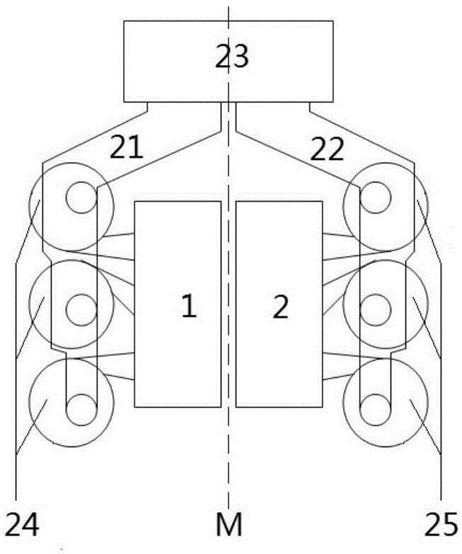
[0018] The present invention provides a double furnace circulating fluidized bed boiler such as figure 1 As shown, it contains two completely independent first furnace 1, second furnace 2, two sets of cyclone separators and a tail convection flue 23; the first furnace and the second furnace are arranged side by side, and there is a gap between the two furnaces There is a certain gap, and there is an independent air distribution device 4 and an air chamber 5 under each furnace; the cross-sectional shape, size and ...


PUM


Abstract

The invention discloses a double-hearth circulating fluidized bed boiler. The double-hearth circulating fluidized bed boiler comprises two completely separate hearths which are arranged side by side; a gap is reserved between the two hearths; a separate air distribution device and an air chamber are arranged at the lower part of each hearth; one group of cyclone separators with the same structures are arranged on the outer side of the surface opposite to each of adjacent surfaces of the two hearths; the two hearths, the two groups of separators and a common connection smoke channel are symmetrically arranged about the vertical center surface of the double-hearth circulating fluidized bed boiler; the two groups of cyclone separators are connected to the same tail convection smoke channel through the common connection smoke channel respectively. According to the double-hearth circulating fluidized bed boiler, single side of each water-cooled walls of each hearth is heated; the heat load difference between parallel tube screens and the table-tilting phenomenon caused by bed pressure fluctuation can be avoided; the reliability and the adjustment flexibility of the control system in the running process are further improved; the power consumption rate of the boiler factory is reduced; the favorable condition is provided for the arrangement of the high-temperature heated surface of the secondarily-heated supercritical circulating fluidized bed boiler; meanwhile, the hearths are simple in design and convenient to enlarge.

Description

technical field [0001] The invention relates to a supercritical large circulating fluidized bed boiler, in particular to a double reheating supercritical circulating fluidized bed boiler, and belongs to the technical field of combustion equipment. Background technique [0002] With the continuous enlargement of circulating fluidized bed boilers and the gradual increase of the furnace scale, the layout of water-cooled walls has become the core issue. Due to the relatively small perimeter of the furnace, the only way to arrange enough water-cooled walls is to increase the height of the furnace. Double-sided heated water wall. From the point of view of combustion, if the furnace height exceeds 45m, the combustion efficiency will not be greatly improved; the height of the tail convection shaft requires the furnace height to exceed 35m, so the furnace height should be kept within 45m as much as possible. The use of double-sided heated water-cooled walls is an effective measure t...

Claims


Application Information

Patent Timeline
Patent Type & Authority Applications(China)
IPC IPC(8): F23C10/00F23C10/18F23C10/20F22B31/08F22B31/04
Inventor 吕俊复张缦黄晓丹杨海瑞岳光溪
Owner TSINGHUA UNIV
Learn More