Gas pipeline safety leak prevention control method

A control method and gas pipe technology, applied in the field of safety valves, can solve problems such as gas explosion, carbon monoxide poisoning, gas leakage, etc.

Active Publication Date: 2017-09-08
陈俊年
View PDF5 Cites 0 Cited by
  • Summary
  • Abstract
  • Description
  • Claims
  • Application Information

AI Technical Summary

Problems solved by technology

[0005] The present invention provides a gas pipeline to solve the problem that existing gas leak detection devices have blind spots when detecting whether gas leaks, and gas leaks into the room while igniting the fire and causing carbon monoxide poisoning or gas explosion. Safe and leak-proof control method

Method used


Image

  • Gas pipeline safety leak prevention control method
  • Gas pipeline safety leak prevention control method

Examples


Embodiment Construction

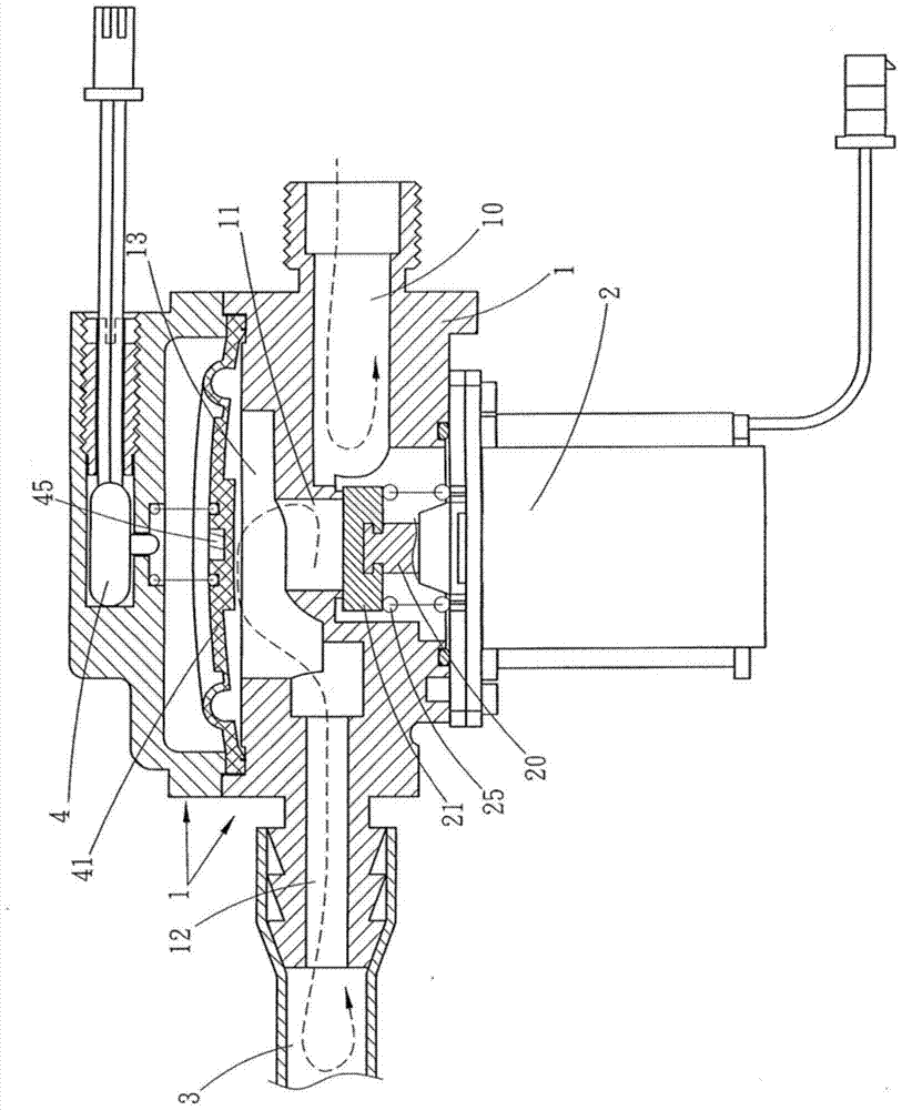
[0017] Attached below figure 1 with figure 2 The present invention is described further:

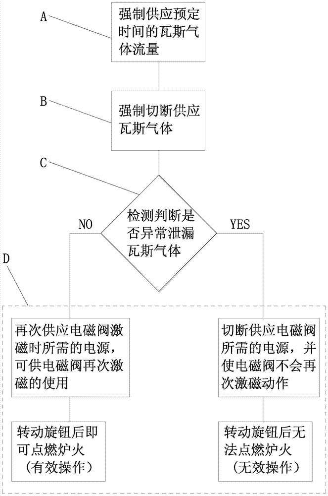
[0018] Such as figure 1 with figure 2 A kind of gas pipeline 3 safety leak-proof control method shown, its method is as follows:

[0019] (A), mandatory supply of gas flow for a predetermined time; before igniting the fire, the electromagnetic valve 2 must be forced to start with a control element (not shown in the figure) to generate an excitation action for a predetermined time, so that it is already located in the electromagnetic valve 2 The piston plate 21 on the shaft rod 20 can be far away from the intake passage 10 of the safety valve 1 (that is, it is in an open state), and allows the gas to flow into the safety valve 1 through the intake passage 10 of the safety valve 1 The air inlet channel 11, the air chamber 13, the air outlet channel 12 and the inside of the pipeline 3. At the same time, the gas that has been located in the air chamber 13 can push the membrane member 4...


PUM


Abstract

The present invention relates to the technical field of safety valves, in particular to a gas pipeline safety leak-proof control method; which at least includes: (A), forcibly supplying the gas flow for a predetermined time; (B), forcibly cutting off the gas supply; (C ), detecting and judging whether the gas gas leaks abnormally; (D), whether to supply the gas gas again; before igniting the fire each time, the electromagnetic valve can be forced to excite for a predetermined time to supply the flow of gas gas flowing into the safety valve and its After the inside of the pipeline, forcefully cut off the power supply required for the excitation of the solenoid valve, and check whether the pressure value remains consistent, as the basis for whether the solenoid valve can be opened again to supply gas flow. In this way, whether it is safety before lighting the fire When there is a large or small leakage inside the valve or its pipeline, the gas supply source of the safety valve can be completely cut off, so as to truly eliminate the phenomenon of carbon monoxide poisoning caused by leakage while using it and prevent the accidental danger of gas explosion.

Description

technical field [0001] The invention relates to the technical field of safety valves, in particular to a safety and leakage prevention control method for gas pipelines. Background technique [0002] The commonly used gas leak detection device, as described in Taiwan Invention Patent Certificate No. I285248, is mainly provided with an excitation device and a magnetic reed switch on one side of the body, and an induction device and a pressure detector on the other side, and the excitation device and the pressure detector are provided on the other side. The device and the pressure detector are connected to the control circuit board in parallel, and can feed back or transmit signals. One side of the body is provided with an inlet leading to the internal valve chamber, and a channel extends from the valve chamber, and the channel is connected to the outlet. , and it is connected to the detection chamber, and a sealing cover is respectively arranged in the valve chamber and the de...

Claims


Application Information

Patent Timeline
Patent Type & Authority Patents(China)
IPC IPC(8): F17D3/01F17D5/02
Inventor 陈俊年
Owner 陈俊年
Why Eureka
Try Eureka