
Machine tool auxiliary mechanical arm

A technology of auxiliary machinery and mechanical arms, applied in the directions of manipulators, program-controlled manipulators, used abrasives processing devices, etc. Simple structure and the effect of avoiding accidental danger

Inactive Publication Date: 2020-06-19
义乌市故宏机械科技有限公司
View PDF0 Cites 0 Cited by
  • Summary
  • Abstract
  • Description
  • Claims
  • Application Information

AI Technical Summary

Problems solved by technology

[0002] With the rapid development of the global economy, my country's economy is also developing rapidly, and the competition among countries is becoming more and more fierce. However, for the manufacturing industry, machine tools are the core of the manufacturing industry, and the development of machine tools in my country is relatively late. The technology has not been studied thoroughly, and it is necessary to improve its own processing technology. Some larger machine tools process heavy parts. It is unrealistic to manually carry these materials. Most of the current solutions use bridge cranes to carry them. These parts and materials, but the bridge crane is relatively heavy and slow, and there are often multiple machine tools in a workshop but only one bridge crane, and the operating efficiency is not high

Method used


Image

  • Machine tool auxiliary mechanical arm
  • Machine tool auxiliary mechanical arm
  • Machine tool auxiliary mechanical arm

Examples


Embodiment Construction

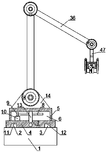
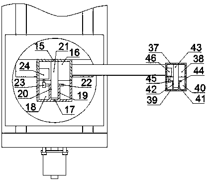
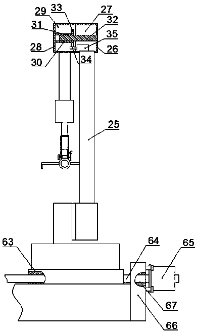
[0017] Combine below Figure 1-5 The present invention is described in detail, and for convenience of description, the orientations mentioned below are now stipulated as follows: figure 1 The up, down, left, right, front and back directions of the projection relationship itself are the same.

[0018] refer to Figure 1-5 According to an embodiment of the present invention, a machine tool auxiliary mechanical arm includes a main body support base 1, and the top of the main body support base 1 is fixed with a first sliding guide rail 2 and a second sliding guide rail 3 extending forward and backward. The sliding guide rail 2 is located on the left side of the second sliding guide rail 3, the upper side of the support base 1 is provided with a sliding platform 4, and the bottom of the sliding platform 4 is provided with a first sliding guide rail matching groove 11 and a second sliding guide rail extending forward and backward. Rail matching groove 12, the first sliding rail ma...


PUM


Abstract

The invention discloses a machine tool auxiliary mechanical arm. The mechanical arm comprises a main body supporting base, wherein the top of the main body supporting base is fixedly provided with a first sliding guide rail and a second sliding guide rail in a front-back extending mode, the first sliding guide rail is located on the left side of the second sliding guide rail, a sliding platform isarranged on the upper side of the supporting base, the bottom of the sliding platform is provided with a first sliding guide rail matching groove and a second sliding guide rail matching groove a front-back extending and through mode, the first sliding guide rail matching groove is connected with the first sliding guide rail in a sliding fit mode, the second sliding guide rail matching groove isconnected with the second sliding guide rail in a sliding fit mode, a rotating table is arranged on the upper side of the sliding platform, flexible and rapid arrival at a designated position can be realized through the mechanical arm, a workpiece is clamped through a clamping mechanism of the tail end, then a machined shaft part in a machine tool is taken out, so that accidental danger which occurs when a worker enters the machine tool to take out the workpiece is avoided, and for some parts which are heavy, it is quick and efficient if the parts are taken by the mechanical arm.

Description

technical field [0001] The invention relates to the related technical field of machine tool auxiliary components, in particular to a machine tool auxiliary mechanical arm. Background technique [0002] With the rapid development of the global economy, my country's economy is also developing rapidly, and the competition among countries is becoming more and more fierce. However, for the manufacturing industry, machine tools are the core of the manufacturing industry, and the development of machine tools in my country is relatively late. The technology has not been studied thoroughly, and it is necessary to improve its own processing technology. Some larger machine tools process heavy parts. It is unrealistic to manually carry these materials. Most of the current solutions use bridge cranes to carry them. These parts and materials, but the bridge crane is relatively heavy and slow, and there are often multiple machine tools in a workshop but only one bridge crane, and the operati...

Claims


Application Information

Patent Timeline
Patent Type & Authority Applications(China)
IPC IPC(8): B25J5/02B25J9/12B24C9/00
CPCB24C9/00B25J5/02B25J9/102B25J9/126
Inventor 魏康
Owner 义乌市故宏机械科技有限公司
Learn More