
Method for producing LOW-E glass by means of vacuum magnetron sputtering

A vacuum magnetron sputtering, glass technology, applied in chemical instruments and methods, glass/slag layered products, layered products, etc. Greening and other problems, to achieve the effect of reducing thickness and production cost

Active Publication Date: 2015-12-16
中建材(内江)玻璃高新技术有限公司
View PDF2 Cites 0 Cited by
  • Summary
  • Abstract
  • Description
  • Claims
  • Application Information

AI Technical Summary

Problems solved by technology

[0003] At present, because most of the float glass used for coating is greenish, the overall color is greenish after coating, and the product transmission color is obviously green or yellow, which causes the outdoor reflection color to turn green or yellow, resulting in the transmission of light The rate is low, but as people continue to pursue visual quality, touch screen products with higher transmittance will have a larger market

Method used


Image

  • Method for producing LOW-E glass by means of vacuum magnetron sputtering
  • Method for producing LOW-E glass by means of vacuum magnetron sputtering
  • Method for producing LOW-E glass by means of vacuum magnetron sputtering

Examples


Embodiment 1

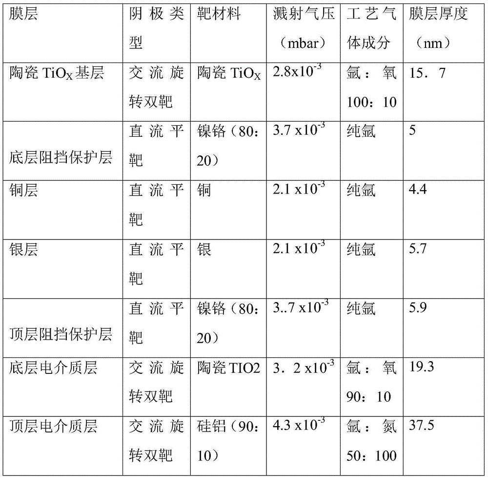
[0040] Table 1 Target position distribution and coating process parameters of coated glass in this embodiment

[0041]

[0042] The optical properties of the LOW-E glass produced by the method of the present embodiment are as follows:

[0043] Visible light transmittance T=60.1﹪; visible light glass surface reflectance 11.5﹪; visible light glass surface color coordinate a*=-2.2; visible light glass surface color coordinate b*=-7.2; visible light transmission color coordinate a*=-0.44; visible light transmission Pass color coordinate b*=-1.17.

Embodiment 2

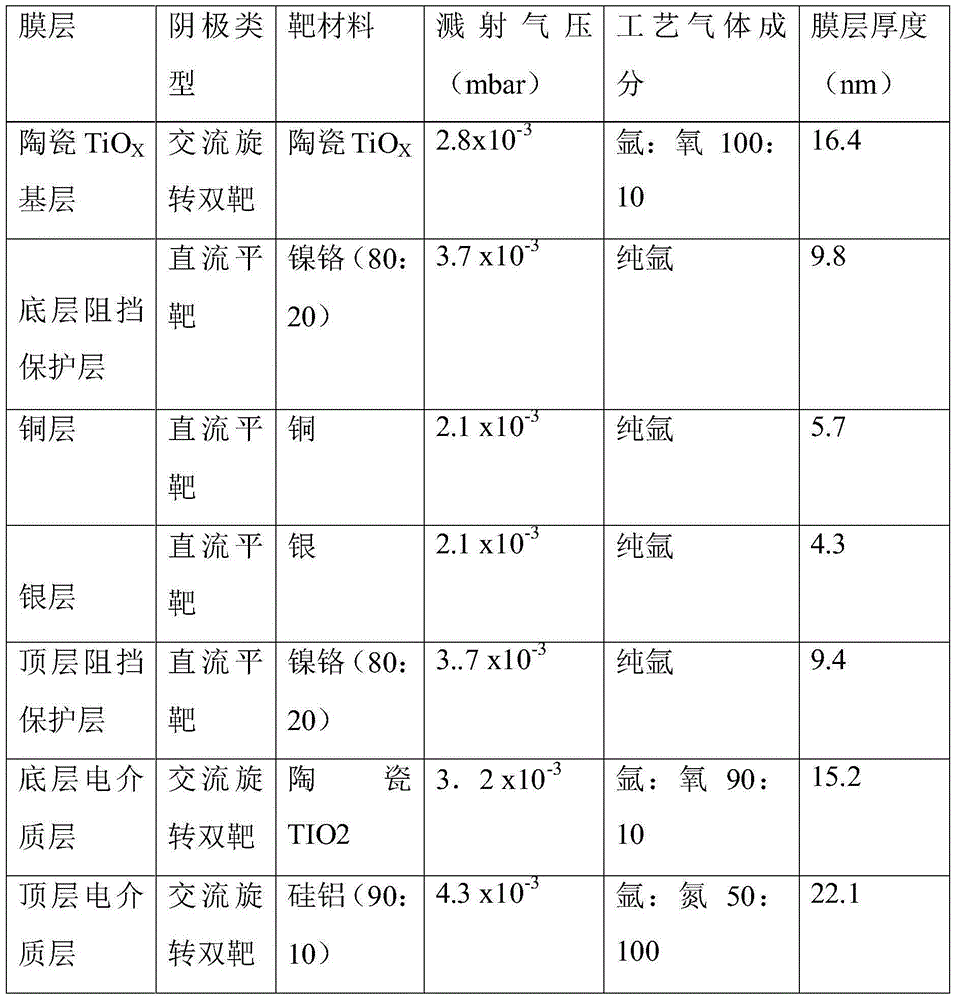
[0045] Table 2 is the target position distribution and coating process parameters of the coating glass of this embodiment

[0046]

[0047]The optical properties of the LOW-E glass produced by the method of the present embodiment are as follows:

[0048] Visible light transmittance T=51.5﹪; visible light glass surface reflectance 18.15﹪; visible light glass surface color coordinate a*=-3.05; visible light glass surface color coordinate b*=-2.95; visible light transmission color coordinate a*=-1.04; visible light transmission Pass color coordinate b*=-1.06.

Embodiment 3

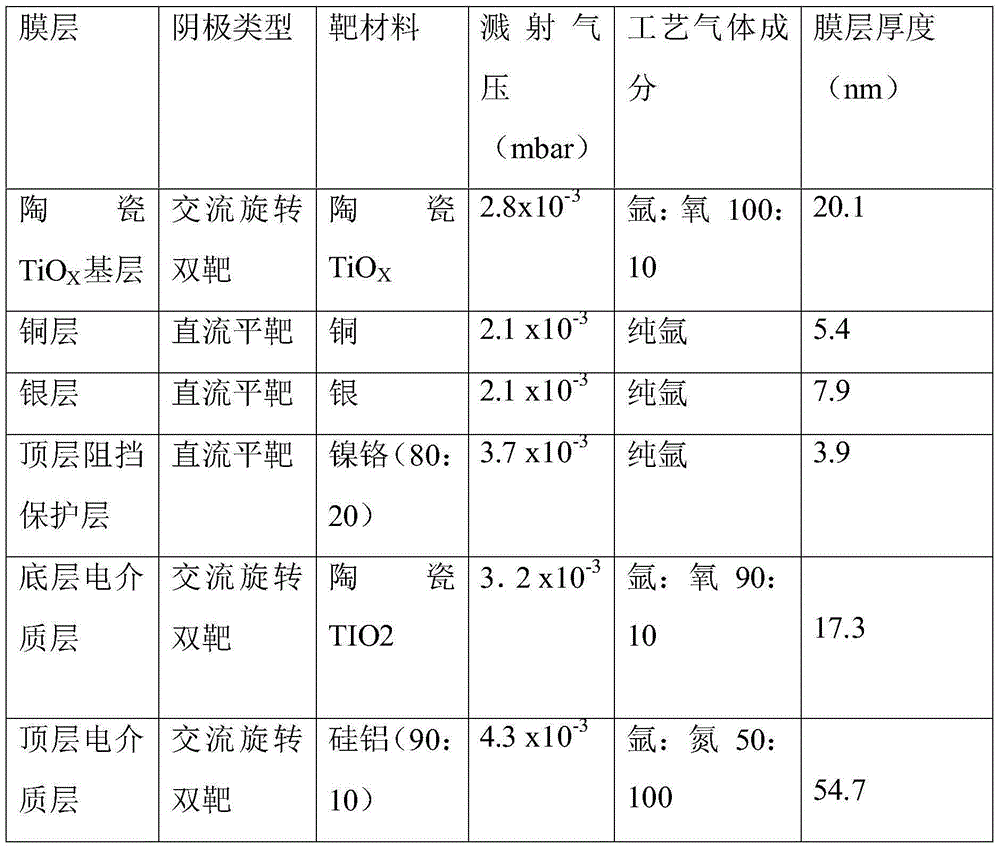
[0050] Table 3 is the target position distribution and process parameters of the coated glass of this embodiment

[0051]

[0052] The optical properties of the LOW-E glass produced by the method of the present embodiment are as follows:

[0053] Visible light transmittance T=64.8﹪; visible light glass surface reflectance 11.35﹪; visible light glass surface color coordinate a*=-2.10; visible light glass surface color coordinate b*=-4.04; visible light transmission color coordinate a*=-0.19; visible light transmission The passing color coordinate b*=0.62.

[0054] To sum up, the Low-E glass produced by this method eliminates the problem of green and yellowish outdoor reflection colors due to the greenish color of the glass substrate, and also greatly improves the refractive index of the Low-E glass.


PUM

PropertyMeasurementUnit
thicknessaaaaaaaaaa
thicknessaaaaaaaaaa
thicknessaaaaaaaaaa

Abstract

The invention discloses a method for producing LOW-E glass by means of vacuum magnetron sputtering. The method comprises the following steps that a cleaned and dried glass substrate is placed in a vacuum chamber of a magnetic control film coating machine; the vacuum degree in the vacuum chamber at least reaches 7.9*10<-6> mbar; the vacuum chamber is inflated with discharge medium gas, and the vacuum degree in the vacuum chamber reaches 2.8*10<-3> mbar-5.0*10<-3> mbar; in a straight argon or argon oxygen atmosphere, a ceramic TiOX base layer is formed on the glass substrate; in a straight argon atmosphere, a bottom blocking and protecting layer is formed on the ceramic TiOX base layer; in the straight argon atmosphere, a copper layer and a silver layer are sequentially deposited on the bottom blocking and protecting layer; in the straight argon atmosphere, a top blocking and protecting layer is formed on the silver layer; in the straight argon or argon oxygen atmosphere, a bottom dielectric layer is formed on the top blocking and protecting layer; in an argon oxygen atmosphere, a top dielectric layer is formed on the bottom dielectric layer.

Description

technical field [0001] The invention relates to coated glass, in particular to a method for producing LOW-E glass by vacuum magnetron sputtering. Background technique [0002] Low-E glass, also known as low-emissivity glass, is a film system product composed of multiple layers of metal or other compounds coated on the glass surface. Its coating layer has the characteristics of high transmission of visible light and high reflection of mid- and far-infrared rays, which makes it have excellent heat insulation effect and good light transmission compared with ordinary glass and traditional architectural coated glass. [0003] At present, because most of the float glass used for coating is greenish, the overall color is greenish after coating, and the product transmission color is obviously green or yellow, which causes the outdoor reflection color to turn green or yellow, resulting in the transmission of light The rate is low, but with people's constant pursuit of visual quality...

Claims


Application Information

Patent Timeline
Patent Type & Authority Applications(China)
IPC IPC(8): B32B17/06B32B37/24
CPCB32B17/061B32B37/24B32B2037/246
Inventor 贺强
Owner 中建材(内江)玻璃高新技术有限公司
Learn More