


Quick Research
Generate reliable direction feasibility study reports for your R&D in just a few steps.

Technical Q&A
Discover and master advanced knowledge NOW. Basics, ideas, possibilities, all at once.

Find Solutions
As an expert in R&D theories, this can generate solutions to your technical problems instantly.

Evaluate Feasibility
Analyze your overall solution with one click, know your potential R&D risks in advance.

Monitor Landscape
Get weekly tech updates, stay abreast of the latest tech innovations and key insights.
External power supply system
A technology for power supply systems and motors, applied in control systems, motors, electrical devices, etc., can solve problems such as power output errors, achieve the effect of improving quality and reducing output errors
- Summary
- Abstract
- Description
- Claims
- Application Information
AI Technical Summary
Problems solved by technology
Method used
Image


Examples
no. 1 example
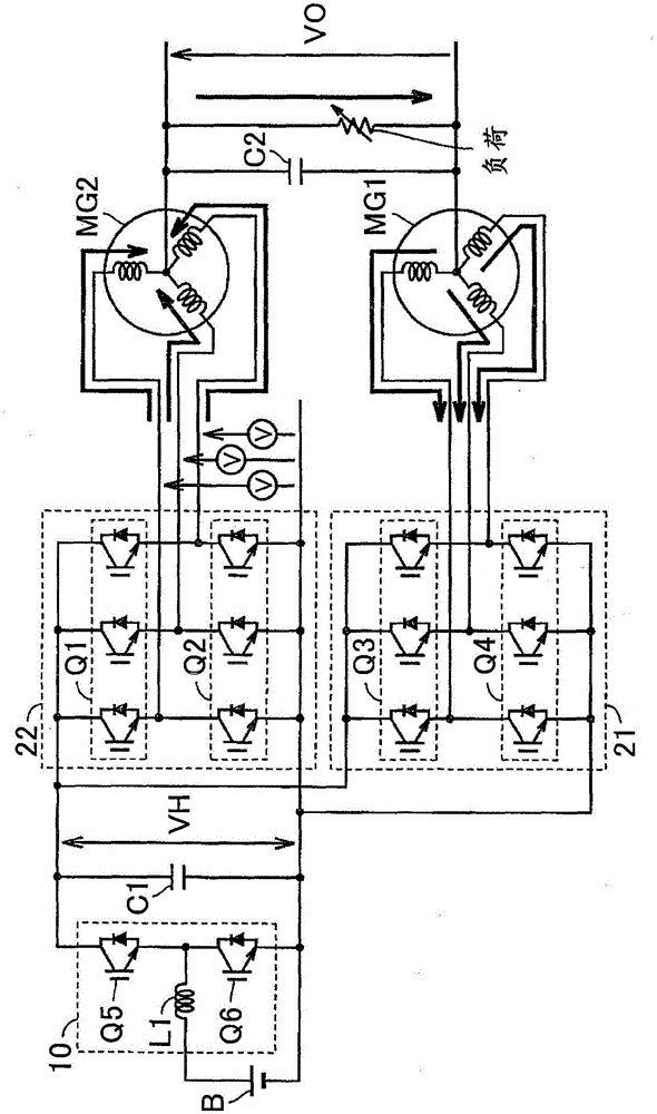
[0050] figure 1 is a block diagram showing the overall configuration of a vehicle to which the external power supply system according to the first embodiment is applied. In the following embodiments, the vehicle is a hybrid vehicle. However, the vehicle according to the present invention is not limited to a hybrid vehicle. like figure 1 As shown, vehicle 100 includes: engine 2 ; motor generators MG1 , MG2 ; power split mechanism 4 ; and drive wheels 6 . Vehicle 100 further includes: power storage device B; system main relay SMR; converter 10 ; inverters 21 , 22 ;
[0051] Vehicle 100 is a hybrid vehicle that travels using engine 2 and motor generator MG2 as power sources. Driving force generated by engine 2 and motor generator MG2 is transmitted to drive wheels 6 .
[0052] The engine 2 is an internal combustion engine such as a gasoline engine and a diesel engine, which outputs power by burning fuel. The engine 2 is configured to be electrically controllable in terms of...
no. 2 example
[0139] In the first embodiment, in order to compensate for an output voltage error or the like during engine operation, control performed based on the inverter current polarity is applied. However, when the current polarity changes at a high rate, if the control is performed after each determination of the current polarity, the control delay affects the voltage compensation.
[0140] Figure 21 is a waveform diagram showing an example where the current ripple is strong and the current polarity fluctuates at a high rate. Figure 21 Shows neutral point output voltage VO and inverter output current igv. In the portion enclosed by the dotted line G, the current changes during the zero crossing and repeatedly reverses its polarity from positive to negative, or negative to positive, at a high rate. In this case, it is difficult to perform feedback control on the polarity of the current. In the second embodiment, instead of performing current polarity determination based on the ou...
PUM
 Abstract
Description
Claims
Application Information
 - R&D Engineer
- R&D Manager
- IP Professional
- Industry Leading Data Capabilities
- Powerful AI technology
- Patent DNA Extraction
Browse by: Latest US Patents, China's latest patents, Technical Efficacy Thesaurus, Application Domain, Technology Topic, Popular Technical Reports.
© 2024 PatSnap. All rights reserved.Legal|Privacy policy|Modern Slavery Act Transparency Statement|Sitemap|About US| Contact US: help@patsnap.com