A feedback drive circuit

A driving circuit and feedback voltage technology, which is applied in the field of step-up high-voltage LED current drive circuit design, can solve the problems of VREF_LED voltage changes greatly and affect power utilization efficiency, etc., so as to save voltage divider feedback resistors, maintain voltage stability, apply simple effects

Active Publication Date: 2017-12-26
SICHUAN YICHONG TECH CO LTD
View PDF3 Cites 0 Cited by
  • Summary
  • Abstract
  • Description
  • Claims
  • Application Information

AI Technical Summary

Problems solved by technology

like Image 6 It is an LED output drive circuit with DAC current regulation function in the prior art. As shown in the figure, when setting different output currents, the VREF_LED voltage changes greatly. If the output drive current needs to change by 10 times, the VREF_LED voltage also needs to be changed. The change is 10 times. In order to ensure the normal operation of the maximum current, it is also necessary to increase the output voltage of Boost, which will also affect the utilization efficiency of this power supply.

Method used


Image

  • A feedback drive circuit
  • A feedback drive circuit
  • A feedback drive circuit

Examples


Embodiment Construction

[0033] The technical solutions of the present invention will be described in further detail below with reference to the accompanying drawings and embodiments.

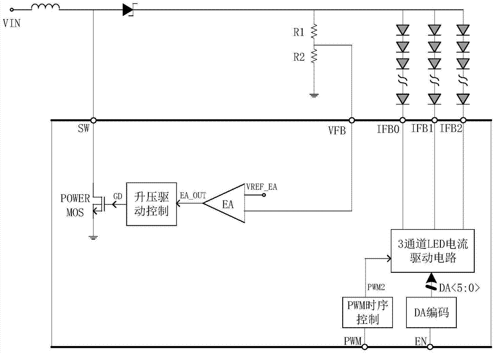
[0034] The circuit of the present invention ensures that the output voltage for driving the LED is high enough without increasing the chip area, and is an optimized output voltage, which fundamentally solves the problem of needing to calculate the feedback voltage divider resistance in different applications; maintains the external circuit The voltage stability not only saves the external voltage divider feedback resistor, but also makes the application simpler and improves the utilization efficiency of the power supply at the same time.

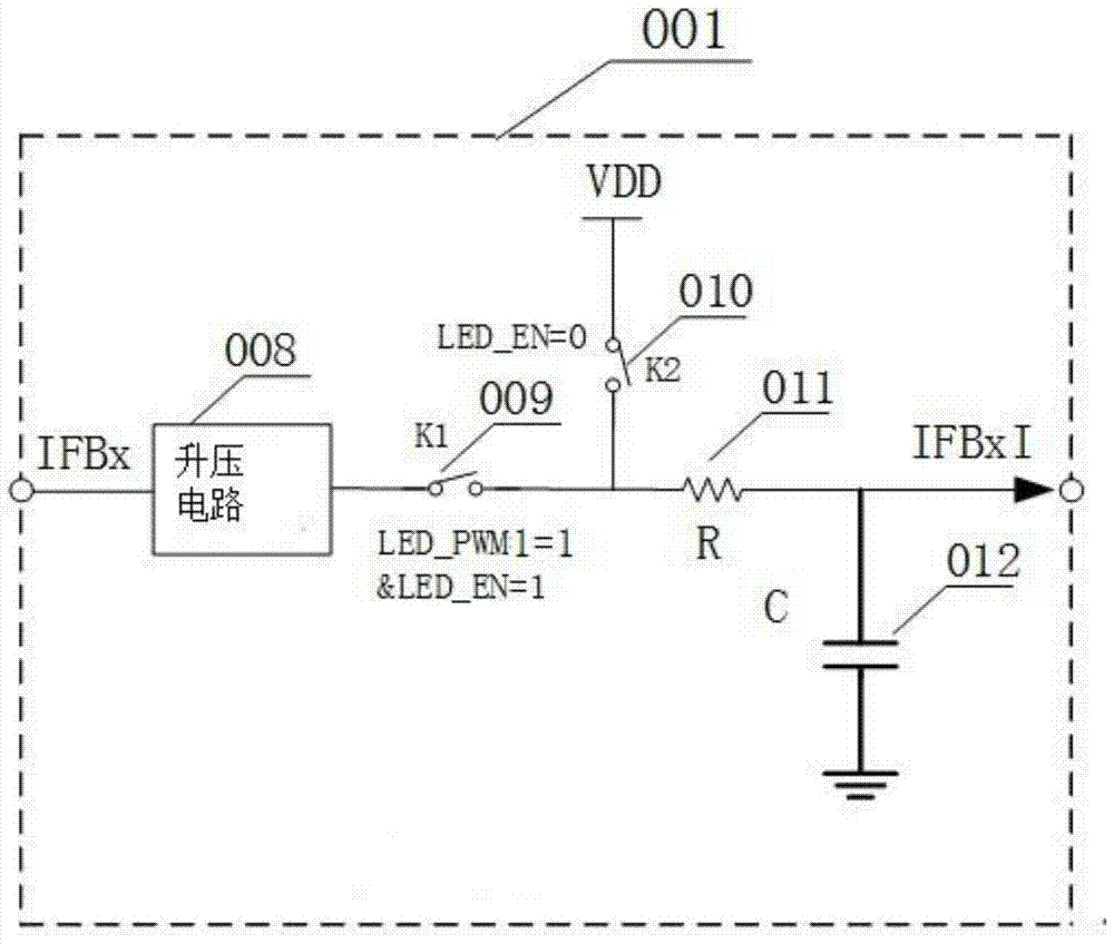
[0035] figure 2 It is a schematic diagram of a feedback driving circuit provided by an embodiment of the present invention. As shown in the figure, a feedback drive circuit includes a channel LED current drive circuit module 003, a boost drive stage circuit module 006, and at least...


PUM


Abstract

The present invention relates to a feedback driving circuit, which comprises a channel LED current driving circuit module (003) for outputting matching currents of at least two LED channels according to a received digital signal; at least two sampling and holding circuit modules (001) , used to collect and hold the node voltages at one end of at least two LED channels respectively; the channel feedback voltage selection and error amplifier module (002) is used to determine the minimum voltage from the voltages output by the at least two sample and hold circuit modules (001), Amplify the minimum voltage and output it; the boosting driver stage circuit module (006) is used to perform a voltage step on the node voltages at the other ends of the at least two LED channels according to the channel feedback voltage selection and the output voltage of the error amplifier module (002). Adaptive adjustment. The invention ensures that the external voltage divider feedback resistance is saved without increasing the chip area, the voltage stability of the external circuit is maintained, the output voltage is optimized, and the utilization efficiency of the power supply is improved at the same time.

Description

technical field [0001] The invention relates to the field of design of boost-type high-voltage LED current drive circuits, in particular to a feedback drive circuit. Background technique [0002] LED backlights are used on small and cheap LCD panels; LED backlight structures are mainly divided into two types, series power supply and parallel power supply. The series power supply can use a lower constant current, but the input power needs to be raised to meet the series The total forward voltage level of the type power supply can drive the LED; the parallel type needs a higher constant current to drive, but reduces the demand for high voltage. Since the current of each LED in the same string is completely equal in the series power supply, there is no current matching problem; while in the parallel power supply, the current on each LED will have a certain deviation, and certain processing needs to be done on the current matching. [0003] The Boost LED driver in the prior art...

Claims


Application Information

Patent Timeline
Patent Type & Authority Patents(China)
IPC IPC(8): H05B37/02
Inventor 杨靖梅当民金学成
Owner SICHUAN YICHONG TECH CO LTD
Why Eureka
Try Eureka