Thermal superconducting heat sink and manufacturing method thereof
A manufacturing method and technology of thermal superconductivity, which are applied in the manufacture/processing of superconductor devices, heat sinks, indirect heat exchangers, etc. Heat dissipation requirements and other issues, to achieve the effect of improving heat dissipation capacity and application range, convenient and flexible manufacturing, and light weight
- Summary
- Abstract
- Description
- Claims
- Application Information
AI Technical Summary
Problems solved by technology
Method used
Image
Examples
Embodiment 1
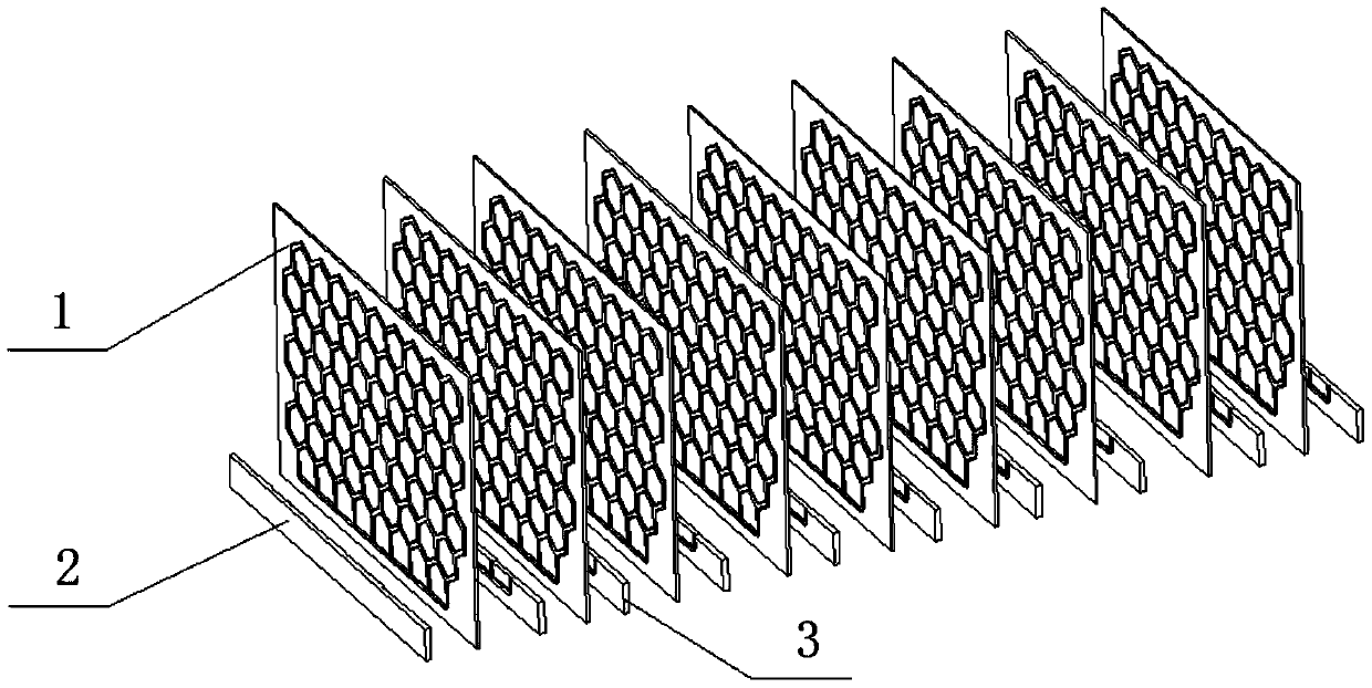
[0073] see Figure 1 to Figure 10 , the present invention provides a thermal superconducting heat sink, the thermal superconducting heat sink includes: several partitions and several thermal superconducting fins 1; wherein
[0074] The separators and the thermal superconducting heat dissipation fins 1 are arranged alternately, and one end surface of the separator is flush with the one end surface of the thermal superconducting heat dissipation fins 1, which jointly constitute a housing suitable for mounting power devices. The mounting surface; the partitions and the thermal superconducting fins 1 between the partitions jointly constitute the substrate of the thermal superconducting heat sink;
[0075] The thermal superconducting heat dissipation fins 1 are fixedly connected with the separator.
[0076] As an example, combine Figure 1 to Figure 3 refer to Figure 4 to Figure 6 , the thermal superconducting heat dissipation fin 1 includes two plates 11 that are composited to...
Embodiment 2
[0091] see Figure 11 , the present invention also provides a thermal superconducting heat sink, the structure of the thermal superconducting heat sink in this embodiment is roughly the same as the structure of the thermal superconducting heat sink described in Embodiment 1, the difference between the two That is: in this embodiment, the shape of the closed pipes 12 in the thermal superconducting heat dissipation fins 1 is a criss-cross network. Figure 11 Each of the quadrilaterals is the non-duct section 15 , and the structures surrounding each of the quadrilaterals and communicating with each other are the closed ducts 12 .
[0092] Other structures and features of the thermal superconducting heat sink in this embodiment are the same as those of the thermal superconducting heat sink described in Embodiment 1. For details, please refer to Embodiment 1, which will not be repeated here.
Embodiment 3
[0094] see Figure 12 , this embodiment also provides a thermal superconducting heat sink, the structure of the thermal superconducting heat sink in this embodiment is roughly the same as the structure of the thermal superconducting heat sink described in Embodiment 1, the difference between the two The point is: in this embodiment, the shape of the closed pipe 12 in the thermal superconducting heat dissipation fin 1 is a plurality of U shapes connected in series from end to end, that is, in this embodiment, the shape of the closed pipe 12 is A shape formed by connecting multiple U shapes end to end. Figure 12 The part below the middle dotted line is the combined part of the thermal superconducting heat dissipation fin 1 and the partition, that is, the part between the partitions, and the interconnected U-shaped structures in the figure are the closed pipes 12. The part located between the closed pipes 12 is the non-pipe part 15. The length direction of the dotted line is t...
PUM
 Abstract
Description
Claims
Application Information
 - R&D
- Intellectual Property
- Life Sciences
- Materials
- Tech Scout
- Unparalleled Data Quality
- Higher Quality Content
- 60% Fewer Hallucinations
Browse by: Latest US Patents, China's latest patents, Technical Efficacy Thesaurus, Application Domain, Technology Topic, Popular Technical Reports.
© 2025 PatSnap. All rights reserved.Legal|Privacy policy|Modern Slavery Act Transparency Statement|Sitemap|About US| Contact US: help@patsnap.com


