
Method for reducing emission of PM2.5 in iron ore sintering flue gas

A technology for sintering flue gas and emissions, applied in the field of iron and steel metallurgy, can solve the problems of huge environmental protection pressure, difficult to capture by electrostatic precipitators, etc., and achieve the effect of reducing emissions

Active Publication Date: 2015-12-09
CENT SOUTH UNIV
View PDF8 Cites 6 Cited by
  • Summary
  • Abstract
  • Description
  • Claims
  • Application Information

AI Technical Summary

Problems solved by technology

[0003] The sintering process mainly uses electrostatic precipitators for the control of flue gas and dust emissions, which can effectively remove coarse particles larger than 10 μm, but because ultrafine particles with a particle size of less than 2.5 μm are easy to load alkali metal chlorides, heavy metal chlorides and CaO, Specific resistance is usually as high as 10 12 -10 13 Ω*cm, difficult to be effectively captured by electrostatic precipitators
In fact, the average emission concentration of flue gas dust from sintering plants in my country is about 102 mg / m 3 , 80% of the dust is ultrafine particle pollutants, and the emission concentration is also in line with the maximum concentration of 50mg / m3 stipulated in the "Steel Sintering and Pelletizing Industry Air Pollutant Emission Standards" 3 There is a large gap in the emission standards of the sintering process PM 2.5 Emission reduction faces huge environmental pressure
[0004] At present, there is no PM at home and abroad for the iron ore sintering process. 2.5 Emission Reduction Research Report, PM 2.5 The research focus of emission control technology is mainly concentrated in the fields of coal combustion and waste incineration. The technical approaches are divided into four types: (1) Reducing PM in the furnace 2.5 generation; (2) agglomeration technology; (3) new dust removal technology; (4) flue gas conditioning technology

Method used


Image

  • Method for reducing emission of PM2.5 in iron ore sintering flue gas

Examples


Embodiment 1

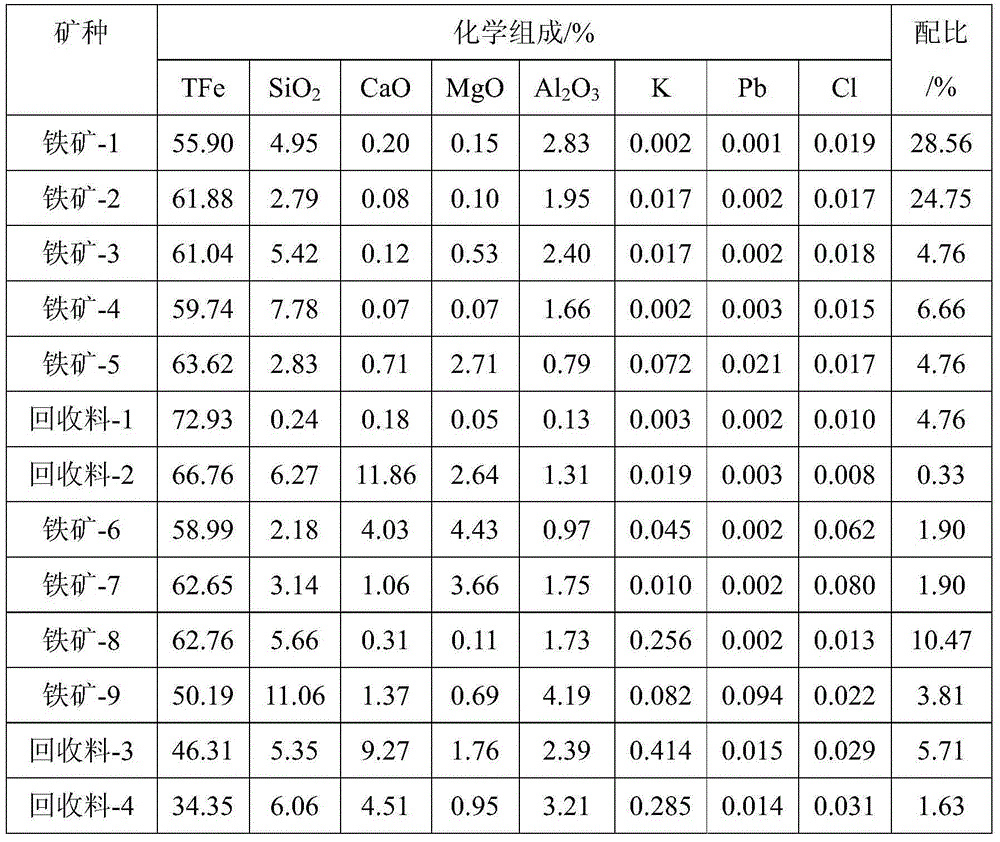
[0030] According to the characteristics of K, Pb, and Cl components in iron-containing raw materials, in Table 1, iron ore-1, iron ore-2, iron ore-3, iron ore-4, iron ore 5, recycled materials-1, recycled materials- 2 is iron-containing raw material with low content of harmful elements, iron ore-6 and iron ore-7 are high-chlorine iron-containing raw materials, iron ore-8, recycled material-3, and recycled material-4 are high-alkali iron-containing raw materials, Mine-9 is a high-lead iron-containing raw material. Iron ore-8, iron ore-9, recycled materials-3, recycled materials-4, quicklime (controlling alkalinity to 2.0) and fuel with a mass fraction of 4% were pre-granulated in a drum mixer for 3 minutes, and then The obtained granulated pellets are mixed with iron ore-6, iron ore-7, iron ore-1, iron ore-2, iron ore-3, iron ore-4, iron ore 5 and recycled material-1, recycled material-2 , return ore, remaining flux and fuel, and kaolin accounting for 2% of the total mass of iro...

Embodiment 2

[0032] According to the characteristics of K, Pb, and Cl components in iron-containing raw materials, in Table 1, iron ore-1, iron ore-2, iron ore-3, iron ore-4, iron ore 5, recycled materials-1, recycled materials- 2 is iron-containing raw material with low content of harmful elements, iron ore-6 and iron ore-7 are high-chlorine iron-containing raw materials, iron ore-8, recycled material-3, and recycled material-4 are high-alkali iron-containing raw materials, Mine-9 is a high-lead iron-containing raw material. Iron ore-8, iron ore-9, recycled materials-3, recycled materials-4, quicklime (controlling alkalinity to 2.2) and fuel with a mass fraction of 3% were pre-granulated in a drum mixer for 4 minutes, and then The obtained granulated pellets are mixed with iron ore-6, iron ore-7, iron ore-1, iron ore-2, iron ore-3, iron ore-4, iron ore 5 and recycled material-1, recycled material-2 , returned ore, remaining flux and fuel, and kaolin that accounted for 3% of the total mas...

Embodiment 3

[0034] According to the characteristics of K, Pb, and Cl components in iron-containing raw materials, in Table 1, iron ore-1, iron ore-2, iron ore-3, iron ore-4, iron ore 5, recycled materials-1, recycled materials- 2 is iron-containing raw material with low content of harmful elements, iron ore-6 and iron ore-7 are high-chlorine iron-containing raw materials, iron ore-8, recycled material-3, and recycled material-4 are high-alkali iron-containing raw materials, Mine-9 is a high-lead iron-containing raw material. Iron ore-8, iron ore-9, reclaimed material-3, reclaimed material-4, quicklime (controlling alkalinity to 2.4) and fuel with a mass fraction of 2% were pre-granulated once in a drum mixer for 5 minutes, and then The obtained granulated pellets are mixed with iron ore-6, iron ore-7, iron ore-1, iron ore-2, iron ore-3, iron ore-4, iron ore 5 and recycled material-1, recycled material-2 , returned ore, remaining flux and fuel, and kaolin that accounted for 4% of the tota...


PUM

PropertyMeasurementUnit
particle sizeaaaaaaaaaa

Abstract

The invention discloses a method for reducing the emission of PM2.5 in iron ore sintering flue gas. According to the method, ferriferous raw materials are divided into high-alkaline-metal ferriferous raw materials, high-lead ferriferous raw materials, high-chlorine ferriferous raw materials and low-harmful-impurity ferriferous raw materials according to the contents of harmful elements such as K (Na), Pb and Cl; the high-alkaline-metal ferriferous raw materials and / or high-lead ferriferous raw materials and raw materials including quicklime are mixed and subjected to primary granulation; granules obtained by primary granulation, the high-chlorine ferriferous raw materials and / or the low-harmful-impurity ferriferous raw materials and raw materials including a silicon-containing solid absorbent are mixed and subjected to secondary granulation; granules obtained by secondary granulation are sintered; and during the sintering process, the granules obtained by secondary granulation can inhibit K (Na) and Pb from being converted into PM2.5 and enhance the PM2.5 adsorption of liquid-phase substances and the solid absorbent, thereby realizing effective control over the emission of PM2.5.

Description

technical field [0001] The invention relates to a method for reducing PM in iron ore sintering flue gas 2.5 The invention relates to an emission method, which belongs to the field of iron and steel metallurgy. Background technique [0002] The iron and steel industry is PM in addition to coal combustion and waste incineration. 2.5 major stationary sources of emissions. Iron ore sintering is an important link in my country's ironmaking process, and its production process exhaust gas accounts for more than 40% of the total waste gas in the iron and steel industry, which is the main source of air pollution in the iron and steel industry. PM emitted from sintering flue gas 2.5 Ultrafine particle pollution, due to PM 2.5 The particle size is small and the specific surface area is large, so it is easy to load toxic and harmful substances such as heavy metal elements (Hg, Pb, Zn, Cr, As), alkali metals (K, Na) and persistent pollutants PCDD / Fs generated during the sintering pro...

Claims


Application Information

Patent Timeline
Patent Type & Authority Applications(China)
IPC IPC(8): C22B1/16
Inventor 范晓慧季志云甘敏陈许玲姜涛李光辉李强周阳何向宁袁礼顺郭宇峰杨永斌张元波李骞黄柱成许斌朱忠平余志元周训伟田志远
Owner CENT SOUTH UNIV
Learn More