A multi-group double-drop double-molding rotary matrix machine

A technology of rotary and row machines, applied in glass forming, glass blowing, glass manufacturing equipment, etc., can solve the problems of single application range, inconvenient use, difficult maintenance, etc., and achieve compact structure of the whole machine and a blanking position The effect of accuracy and low equipment failure rate

Active Publication Date: 2017-06-13
湖北楚大智能装备股份有限公司
View PDF5 Cites 0 Cited by
  • Summary
  • Abstract
  • Description
  • Claims
  • Application Information

AI Technical Summary

Problems solved by technology

[0006] (1) For different glass forming processes, the existing rank-and-file machines cannot fully and quickly cool glass bottles of different forming processes, and the scope of application is relatively single
[0007] (2) The existing numerical control bottle machine is an independent single structure. The bottle making machine is spliced ​​and installed at the production site. The installation accuracy is poor and the installation cycle is long, so it is difficult to ensure the accuracy of the blanking position
[0008] (3) The rotary gas distribution electric slip ring of the existing digital control bottle machine is installed on the center column between the upper and lower turntables of the forming mold part, which is difficult to maintain and is not convenient for people to use
[0009] (4) The existing line-of-sight machine adopts the method of one set of initial molds corresponding to one set of molds. The time required for glass forming is long, the production efficiency is low, and it cannot meet the high-efficiency production mode.
[0010] (5) The existing digital control bottle machine adopts pneumatic clamp bottle, the air pressure stability of pneumatic clamp bottle is poor, and the response speed is slow

Method used


Image

  • A multi-group double-drop double-molding rotary matrix machine
  • A multi-group double-drop double-molding rotary matrix machine
  • A multi-group double-drop double-molding rotary matrix machine

Examples


Embodiment Construction

[0059] The present invention will be described in further detail below in conjunction with the accompanying drawings and embodiments.

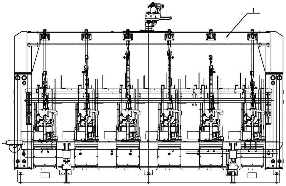
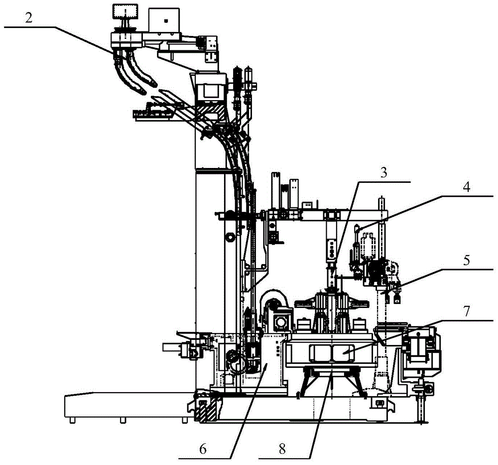
[0060] see figure 1 As shown, multiple groups of double-drop double-molding rotary row machines in the embodiment of the present invention include a main frame 1; see figure 2 As shown, the main frame 1 is provided with 2 to 10 sets of servo turntable mechanisms 8, and the top of the servo turntable mechanisms 8 is provided with a composition-type side upper turntable mechanism 7, and the top of each composition-type side upper turntable mechanism 7 is provided with an oil-air slip ring Component 3. see figure 2 and image 3 As shown, the main frame 1 is also equipped with a double drip system 2, an electronic bottle shifting conveyor belt 9, 2 to 10 sets of rotating bottle holding mechanisms 4, 2 to 10 sets of servo bottle clamp mechanisms 5 and 2 to 10 sets of prototypes Side box assembly 6.

[0061] The servo turntable mechanism 8, t...


PUM


Abstract

The invention discloses a multi-set double-dropping and double-molding rotary type individual section machine, and relates to the field of individual section machines for producing glass bottles. The individual section machine comprises a main machine frame. Two to ten servo rotary plate mechanisms are arranged on the main machine frame. A forming side upper rotary plate mechanism is arranged on the top of each servo rotary plate mechanism. An oil-gas slide ring assembly is arranged on the top of each forming side upper rotary plate mechanism. A double-dropping material flowing system, an electronic bottle pulling conveying belt, two to ten rotary bottle supporting mechanisms, a servo bottle clamping mechanism and a primary side box body assembly are further arranged on the main machine frame. The forming side upper rotary plate mechanisms, the oil-gas slide ring assemblies, the rotary bottle supporting mechanisms, the servo bottle clamping mechanism and the primary side box body assembly correspond one to one. By means of the individual section machine, formed molds can be fully and rapidly cooled in different glass forming processes, the application range is wide, the whole machine is compact in structure, gas, oil and electricity are integrally supplied, installation and maintenance are convenient and rapid, the device failure rate is low, installation space is compact, forming time is short, production efficiency is high, and material falling position is accurate.

Description

technical field [0001] The invention relates to the field of matrix machines for making glass bottles, in particular to a rotary matrix machine with multiple sets of double drops and double molds. Background technique [0002] In the glass bottle making industry, glass bottle making is a kind of equipment that molds molten glass frit into various glass bottles and jars (such as glass wine bottles, glass perfume bottles, glass beer pots, glass jars, etc.). [0003] Existing rank machine includes main frame part, primary forming mold part, hydraulic turning mechanism, pneumatic pincer bottle part. The frame of the primary forming mold part is connected with the frame chassis through a small bottom plate; the hydraulic turning mechanism is installed in the frame hole of the primary forming mold part; the pneumatic clamp bottle is installed on the side of the frame of the primary forming mold part. [0004] Existing numerically controlled bottle machine includes frame part, pre...

Claims


Application Information

Patent Timeline
Patent Type & Authority Patents(China)
IPC IPC(8): C03B9/13
Inventor 郭云飞刘虎邓智彭安乐梁国俊
Owner 湖北楚大智能装备股份有限公司
Why Eureka
Try Eureka