Cyclonic anaerobic reaction apparatus, AMBR sewage treatment system and sewage treatment method

A technology of anaerobic reaction device and sewage treatment system, applied in anaerobic digestion treatment, water/sewage multi-stage treatment, water/sludge/sewage treatment, etc. Problems such as uneven distribution of oxygen sludge

Inactive Publication Date: 2015-12-09
宁夏祥河生态环境工程研究院有限公司
View PDF5 Cites 1 Cited by
  • Summary
  • Abstract
  • Description
  • Claims
  • Application Information

AI Technical Summary

Problems solved by technology

[0003] The anaerobic reaction tank of the traditional process is a large closed reaction tank, which includes a water inlet at the bottom of the tank and a water outlet higher than the water inlet. During the anaerobic reaction, the sewage continuously enters the anaerobic reaction tank from the water inlet. In the reaction tank, the anaerobic sludge containing anaerobic organisms deposited at the bottom of the pool is washed away and reacted under the action of anaerobic organisms. Finally, the reacted sewage floats up to the height of the water outlet and is discharged from the water outlet. There is also anaerobic sludge discharged from the outlet. During this reaction process, due to the limited time for the sewage to reach the outlet from the bottom of the pool, the contact time with anaerobic organisms is short. Moreover, due to the uneven distribution of anaerobic sludge, some The pool water may not be exposed to anaerobic organisms, which limits the effective anaerobic treatment of sewage and also causes anaerobic sludge loss

Method used


Image

  • Cyclonic anaerobic reaction apparatus, AMBR sewage treatment system and sewage treatment method
  • Cyclonic anaerobic reaction apparatus, AMBR sewage treatment system and sewage treatment method
  • Cyclonic anaerobic reaction apparatus, AMBR sewage treatment system and sewage treatment method

Examples


Embodiment Construction

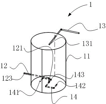
[0025] Please also refer to figure 1 , The cyclone anaerobic reaction device 1 provided by the embodiment of the present invention is characterized in that it includes a sealed reactor shell 11, an inlet pipe 12, an outlet pipe 13, and is located in the reactor shell 11 and arranged parallel to the reactor shell. The distribution pipeline 14 at the bottom of the body 11, the distribution pipeline 14 at least includes a pair of first water outlet 141 and the second water outlet 142 arranged in opposite directions, the distribution pipeline 14 is also provided with an outlet pipe connection port 143, and the water inlet pipe 12 passes through the reaction The side wall of the reactor housing 11 and the water outlet 121 of the water inlet pipe 12 are connected with the water outlet connection port 143 of the shunt pipe 14, the water outlet pipe 13 passes through the side wall of the reactor housing 11 and the water inlet 131 of the water outlet pipe 13 is located in the reactor. ...


PUM


Abstract

A cyclonic anaerobic reaction apparatus is provided by the present invention and comprises a sealed reactor housing, a water inlet pipe, a water outlet pipe and a shunt conduit that is located inside the reactor housing and that is disposed parallel to the bottom of the reactor housing. The shunt conduit comprises at least one pair of a first water outlet and a second water outlet which are arranged in opposite directions. A water outlet pipe connection port is further disposed on the shunt conduit. The water inlet pipe passes through a side wall of the reactor housing and a water outlet of the water inlet pipe is connected to the water outlet pipe connection port of the shunt conduit. The water outlet pipe passes through the side wall of the reactor housing and a water inlet of the water outlet pipe is located inside the reactor housing. The water inlet of the water outlet pipe is higher than the shunt conduit. The reactor housing is filled with anaerobic sludge. When traveling through a water inlet pipe connection port, the sewage is shunted by the shunt conduit, and meanwhile flows out in opposite directions through the first water outlet and the second water outlet, so that a swirling flow is formed inside the reactor housing so as to increase the contact area between the sewage and the anaerobic sludge. The present invention further provides an AMBR sewage treatment system and a sewage treatment method.

Description

technical field [0001] The invention relates to the technical field of sewage treatment, in particular to a cyclone anaerobic reaction device, an AMBR (Anaerobic Membrane Biological Reactor, anaerobic membrane bioreactor) sewage treatment system and a sewage treatment method. Background technique [0002] Sewage treatment personnel are committed to improving the advanced sewage treatment process and reducing the instability and safety hazards caused by nitrogen and phosphorus pollutants to reclaimed water. The traditional denitrification and phosphorus removal process is realized through anaerobic reaction and aerobic reaction. Among them, the anaerobic reaction is to make the sewage flow into the anaerobic reaction tank, and the anaerobic organisms in the anaerobic reaction tank complete the various pollutants in the sewage. Complex organic molecules are transformed into organic matter and released after release of phosphorus. The aerobic reaction is to make the sewage afte...

Claims


Application Information

Patent Timeline
IPC IPC(8): C02F3/28C02F9/14
CPCY02W10/37
Inventor 王德全胡定国
Owner 宁夏祥河生态环境工程研究院有限公司
Why Eureka
Try Eureka